AC/DC Module
Placed my Mouser order")
Mouser won't ship the Mean Well AC/DC module to the UK due to CE restrictions. It looks like the RECOM RAC02-05SE/277 would work as a replacement - is this correct?
Link to product page.
Thanks for your help.
Placed my Mouser order
Mouser won't ship the Mean Well AC/DC module to the UK due to CE restrictions. It looks like the RECOM RAC02-05SE/277 would work as a replacement - is this correct?
Link to product page.
Thanks for your help.
If UK Mouser won't sell it to you then you will need to find another UK distributor with parts on the shelf, who will sell to you. Sitting here on my couch in California, I managed to find two: RS Components UK and Farnell UK.
49 units in stock at RS @ £4.81
941 units in stock at Farnell @ £4.91
I recommend you buy from both, just to find out which one is easier to deal with. Good info to have for future audio hobby purchases!
49 units in stock at RS @ £4.81
941 units in stock at Farnell @ £4.91
I recommend you buy from both, just to find out which one is easier to deal with. Good info to have for future audio hobby purchases!
10 PCBs available for shipping to US-50
Hello All -
I have 10 PCBs left for members who are interested. Send me a PM if you would like to get them.
Regards,
Subbu
Hello All -
I have 10 PCBs left for members who are interested. Send me a PM if you would like to get them.
Regards,
Subbu
PCBs ordered on Tuesday and will update once I receive them from the board house. PCBs are 2 oz Copper with ENIG. I will send a pm to the members shown interest with Paypal details.
I have ordered 10 extra, in case some other members need them. Interested members please pm me.
Cost per PCB will be $4.00 + shipping 4 - 5 to US domestic First class package service.
Cheers!
Subbu
NO,NC
I am totally lost as to the switch wiring(fr post #16) on this project. Nothing at Newark. Part of it is probably how you use the switch. The switch is push for on and push again for off. It's 2 pole. 2NO, 2NC, 2C and a +-. To me, the switch is normally open. Don't even know why you wire an open circuit but there are posts for it.
I need help with this including the led wiring
Thanks,
Don
I have obtained the boards (2 monoblocks) and stuffings, and have studied the PCB and schematic. But I am far from the most knowledgeable.
This board can be configured to use a low voltage rated switch of most any variety. You can get a simple toggle switch, latching pushbutton, or a momentary contact switch. There is a place on the board to connect that will enable the momentary switch (anything that makes electrical contact when you touch it), using logic on the board to open and close the main relay. There are 2 LED sets, one that lights the LED when the power is on, and one that will light the LED when the power is off. (some switches have lights for the various states). You could get one of the non-lighted switches, and power an LED mounted on the front plate of the amplifier.
So, firstly, decide what you want your switch to do, and how do you want it to look, and what are the LEDs supposed to do. This board can pretty much make whatever you envision to work properly.
Bones, good to hear from you. I hope things are getting back to normal for you.
"Elective" surgery is way off in our neck of the woods. People would rather stay out of the hospital. Compounded by draconian visitation rules. Moving on...
Thanks for the response. I have the switches from the #16 post but I can't figure out how to wire them in conjunction with the boards.
Don
"Elective" surgery is way off in our neck of the woods. People would rather stay out of the hospital. Compounded by draconian visitation rules. Moving on...
Thanks for the response. I have the switches from the #16 post but I can't figure out how to wire them in conjunction with the boards.
Don
To successfully apply a foreign, mysterious, undocumented, confusing pushbutton switch:
The always-works, never-fails method is to use an ohmmeter or continuity buzzer, to find the pair of terminals which are not-shorted-together when the button isn't pushed, and which also are-shorted-together when the button is pushed.
You can ignore whatever is engraved on the switch, in whatever language the engraver spoke, and you can ignore any mistakes or ambiguities in his labeling. Just find the pair that works for YOU, write it down in your permanent notebook, including a drawing, and that's that.
it works
Thank you Mark. It works. In my case, NO (normally open) sets the correct logic. Gotta love the terminology. But, you are right. The proof is in the pudding.
Thank you.
Now for the board part.
The switch has a led with +-. I can power the led and it turns on - no matter what. If I connect your Led on lead to the switches +- will the led go on and off with the switch. That is on with the switch on and off with the switch off. I guess I could Power the board up with a trafo and do the same DMM test and see what happens.
Got my scope and am going to Q test jig all my trafos so retro fitting all my PS's
with snubbers.
My to do list is getting longer.
Thanks for your help and thanks for the projects.
Regards,
Don
To successfully apply a foreign, mysterious, undocumented, confusing pushbutton switch:
The always-works, never-fails method is to use an ohmmeter or continuity buzzer, to find the pair of terminals which are not-shorted-together when the button isn't pushed, and which also are-shorted-together when the button is pushed.
You can ignore whatever is engraved on the switch, in whatever language the engraver spoke, and you can ignore any mistakes or ambiguities in his labeling. Just find the pair that works for YOU, write it down in your permanent notebook, including a drawing, and that's that.
Thank you Mark. It works. In my case, NO (normally open) sets the correct logic. Gotta love the terminology. But, you are right. The proof is in the pudding.
Thank you.
Now for the board part.
The switch has a led with +-. I can power the led and it turns on - no matter what. If I connect your Led on lead to the switches +- will the led go on and off with the switch. That is on with the switch on and off with the switch off. I guess I could Power the board up with a trafo and do the same DMM test and see what happens.
Got my scope and am going to Q test jig all my trafos so retro fitting all my PS's
with snubbers.
My to do list is getting longer.
Thanks for your help and thanks for the projects.
Regards,
Don
Does anyone have extra PCBs who would be willing to send to Spain?
I would be happy to do an order myself (maybe in an exotic color!), but mailing from Spain is so expensive it would be hard to offer attractively priced boards to others (incl. postage).
Also, I already have the DiyAudioStore soft start board built and working, so if anyone has a recommendation for a power switch relay only board, please PM me.
Last edited:
For relay on/off only, I use this but I don't know if you have 12V control voltage there already.
12V Bond Button Bistable Relay Module Car Start/Stop Self-Locking Switch | eBay
I use this for the 12V if I don't already have it.
12V 500mA AC-DC Power Supply Converter Step Down Module Electronic Transformer | eBay
12V Bond Button Bistable Relay Module Car Start/Stop Self-Locking Switch | eBay
I use this for the 12V if I don't already have it.
12V 500mA AC-DC Power Supply Converter Step Down Module Electronic Transformer | eBay
> the switch is normally open. Don't even know why you wire an open circuit but there are posts for it. ...... snip ...... In my case, NO (normally open) sets the correct logic. Gotta love the terminology.
"Normal" is sitting there, you not touching it.
When you TOUCH it, it is not "normal".
So "Normally Open", "TOUCHED", is logically "closed". Passes current.
Simplest-case, works like a door-bell.
In this case, Mark put in more stuff for alternate action.
"Normal" is sitting there, you not touching it.
When you TOUCH it, it is not "normal".
So "Normally Open", "TOUCHED", is logically "closed". Passes current.
Simplest-case, works like a door-bell.
In this case, Mark put in more stuff for alternate action.
I would like to take the this time to commend Mark for his unwavering generosity by offering such a fine piece of engineering for free use to our community. Random acts of kindness that mean so much to people who do not possess the ability to create such useful, highly engineered pieces of art that makes me want to give praise to someone who honestly deserves it.
I’m sure I speak for many people here... Mark, thanks for being YOU!
*I would be interested in a single unit (220 volt version) if there’s anyone in or close to the Philippines willing to sell. Shoot me a PM!
I’m curious, how much is the cost of all the parts & pieces including the board itself?
I’m sure I speak for many people here... Mark, thanks for being YOU!
*I would be interested in a single unit (220 volt version) if there’s anyone in or close to the Philippines willing to sell. Shoot me a PM!
I’m curious, how much is the cost of all the parts & pieces including the board itself?
I added the soft start board in circuit with my Tubelab SSE and it powered up just as it should but I noticed that B+ is 10V lower than before. Without the board when I turned the power on B+ would spike to 500V then drop down to 430V. With the soft start board at power on the volts spike to 480V, then drop down to around 400V, then very slowly climb to about 420V. Does this make any sense or have I got something wrong?
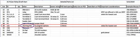
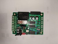
Spiggs it sounds like your bypass relay might not be engaging. As though there is an assembly error or a bad component somewhere in the relay coil circuitry. Did you remember to install a shorting-block to select a bypass option (0.5, 1.0, 2.0 sec) ?? Do you hear the relay make a click sound?
One of the simple tests for H9KPXG that I found useful, was to disconnect the transformer primary(s) and instead, connect a >= 100 watt incandescent light bulb as the load. At turn-on, the bulb comes on bright, goes half dim, and gradually grows brighter. Then, at t=2.0 seconds, the bypass relay engages and (a) you hear an audible click; (b) the bulb goes to full brightness. This might be a quick and easy diagnostic test to check whether your bypass is working correctly.
_
Attachments
Spiggs it sounds like your bypass relay might not be engaging. As though there is an assembly error or a bad component somewhere in the relay coil circuitry. Did you remember to install a shorting-block to select a bypass option (0.5, 1.0, 2.0 sec) ?? Do you hear the relay make a click sound?
One of the simple tests for H9KPXG that I found useful, was to disconnect the transformer primary(s) and instead, connect a >= 100 watt incandescent light bulb as the load. At turn-on, the bulb comes on bright, goes half dim, and gradually grows brighter. Then, at t=2.0 seconds, the bypass relay engages and (a) you hear an audible click; (b) the bulb goes to full brightness. This might be a quick and easy diagnostic test to check whether your bypass is working correctly.
_
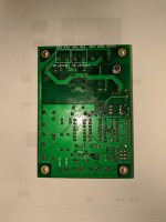
Shorting block is installed at t=2 and I tried the 100w bulb test. Plug it in then hit the switch and bulb comes on, 2 seconds later I hear a click. Don't notice the bulb getting dimmer, or brighter. i also measured volts in at ~119, volts out ~113 after the click with bulb lit. Attached are pics of my board.
Attachments
- Home
- Amplifiers
- Power Supplies
- PCB: low voltage On-Off switch drives AC mains relay \ includes soft start .. H9KPXG