I got fed up with DIY power amps whose AC mains On-Off switch is on the rear panel. This choice does reduce the amount of metal working required; just buy an all-in-one plastic molded unit containing IEC inlet jack, fuse holder, and AC mains rated switch. Cut one rectangular hole in the rear panel (where small mistakes in drilling or filing are not visible!), drop in the unit, done! But reaching through the equipment rack to operate a switch on the back panel is clumsy to watch, and awkward to do. I wanted something a little more refined.
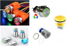
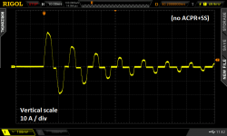
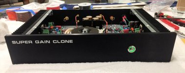
Front panel switches with a circular pushbutton and colored illumination looked promising; the type called "Anti-Vandal" appealed to me. Figure 1 shows a few examples of them. UNFORTUNATELY, most of these switches are rated for low current DC applications like soda vending machines; very few are rated for AC mains switching at the high currents needed by power amplifiers. Worse yet, the inrush current that flows through the On-Off switch at the instant when the gear is turned on, can be enormous. Far too high for a switch rated 2A @ 24VDC. Figure 2 shows the measured AC mains current which flows, when a rather modest chipamp-based power amp (photo) is turned on. The inrush current peak is 24 amperes: (2.4 vertical div X 10 Amps per div). That's quite a stress for everything in the AC mains current path, including the On-Off switch's contacts. And remember, this is not some super-amp behemoth from Krell; it's just an Antek 200VA toroid, two LM3886 amp channel boards, and a diyAudio Universal Power Supply PCB. Yet its inrush current is frighteningly large.
It seemed to me the only way to use the Anti-Vandal On-Off switches I liked, was to use them at low current & low voltage. They wouldn't directly switch the mains; instead they would merely control a separate big, robust, high-current and high-AC-voltage switch. Perhaps such as a mains rated relay or triac.
Regrettably, more than half of these Anti-Vandal switches are momentary pushbuttons; they don't have latch-in-position action like rocker switches or toggle switches. To use them on the front panel of a power amp, an electronic latch or flipflop would be needed, giving "push on, push off" behavior.
SMALL LIGHTWEIGHT FRONT PANEL SWITCHES
Nelson Pass's 1992 amplifier DIY project called A75 (class-A, 75W/ch) used a triac to switch the AC mains off and on. The triac was controlled by a small front panel switch. The circuit reduced switch current to single digit milliamps, but it did require a front panel switch that can withstand the full AC mains voltage (230V in many countries). Very few of the Anti-Vandal switches meet this requirement, unfortunately.
Canadian high-end power amp manufacturer Bryston used an always-on, micropower, low voltage DC supply for their front panel power switch. It fires a triac, and the triac switches the AC mains on and off.
Australian engineer and prolific DIY project creator Rod Elliott offers Project 166 which is a Push-On, Push-Off Mains Switch. It includes an always-on, micropower, 12V DC supply. This powers a logic flipflop circuit which is the memory element for the push-push function. The flipflop operates a 12V relay, whose hefty contacts switch the AC mains on and off.
INRUSH CURRENT LIMITING WITH BYPASS
The measured inrush current waveform in Figure 2 indicates to me that some type of inrush current limiting is certainly needed, no matter how beefy and robust an on-off relay or triac is used. I still want to avoid over-stress of the transformer, the mains fuse, the internal wiring, etc.
I decided to also include a bypass circuit, which completely removes the inrush current limiter a short time after power on, when mains current has settled down to its normal (non-inrush) condition. Both Douglas Self's textbook and also Bob Cordell's textbook recommend inrush bypass circuits, on their page numbers 633 and 459, respectively. Bypassing the ICL reduces its current to zero, so it cools down and becomes ready for the next power-on event (a so-called "hot restart"). Bypassing the ICL also reduces the voltage dropped across it (to zero), which can be significant when the rectifier current-peaks are large. See Cordell p.459 for more.
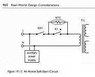
The basic idea of inrush current limiting with bypass is sketched in Figure 3. Switch "SW1" turns the amplifier On and Off. Series resistor "NTC" performs the function of inrush current limiting. It guarantees that mains current cannot possibly exceed (Vmains / R_NTC) even if the rest of the primary circuit is an ideal short circuit. Switch "K1" bypasses the inrush current limiter after the inrush event has completed and mains current is down to its normal levels.
Inrush limiters have been successfully deployed using (a) ordinary wirewound resistors [Self], and also (b) specialized Inrush Current Limiter components [Cordell]. I decided to use option (b), the special ICL components. They offer a degree of extra safety in case the bypass mechanism fails open-circuit: an ICL can withstand the full primary current indefinitely. Whereas (a) wirewound resistors would self-destruct in less than one minute.
In construction, ICLs are enormous Negative Temperature Coefficient thermistors; a famous example is the CL-60, whose very part number includes CL for Current Limiter. I prefer not to refer to these as thermistors, to avoid confusion with the tiny little temperature sensors that also happen to have a negative temperature coefficient. So I will make an effort to always say "Inrush Current Limiter". Oh by the way, that happens to be the name that both Digikey and Mouser give to the section of their website where these components are sold. Forget Thermistor, remember Inrush Current Limiter.
When should the inrush limiting cease? When should the bypass turn on? Opinions vary. Texas Instruments bypasses the ICL when the amplifier's DC power rails have ramped up to approx. 60% of their final voltage (Fig.5 on p.7). Self suggests bypassing 1 second after power-on (p. 632). Rod Elliott's inrush current limiter for power amps, Project 39, enables the bypass after 0.1 seconds. A brief and incomplete survey of diyAudio discussion threads, turns up recommendations varying between 10 full cycles of the AC mains (0.2 sec) and 100 cycles of the mains (2.0 sec). All of this suggests to me that there are probably more than one right answer, and maybe the shrewd decision is to provide a few user-selectable options. As has previously been done in the Soft As A Feather Pillow soft start design by diyAudio members jhofland and xrk971, I chose the convenient 2X-per-step settings 0.5 sec, 1.0 sec, 2.0 sec. Thus bypass happens either 0.5, 1.0, or 2.0 seconds after power on, selected by a jumper on the PCB.
CIRCUIT SCHEMATIC DIAGRAM
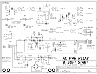
Figure 4 is the schematic of this PCB. The power handling "business end" of the circuit in on the bottom half of the page; the top half is merely timing and LED management.
The actual front panel switch connects at top left; it switches only 5V DC at 0.5 milliamperes. This ripples through some digital logic gates and produces a digital signal "TRIAC_B", which turns on triac T1 through opto isolator U4. When T1 turns on, it applies mains power to the transformer primary windings. Notice that triac T1 is series connected with an Inrush Current Limiter device, "ICL1".
Component ICL1 a 22mm diameter device made by Ametherm, whose surge energy rating is 125 Joules. For 115V applications I recommend part number SL22-20007, whose cold resistance is 20 ohms and whose max continuous current is 7 amps. Thus the inrush current when the ICL is at room temperature, cannot exceed (115 / 20) = 5.8 amps, and that assumes the transformer primary, mains fuse, and AC wiring all add up to 0.00 ohms of additional resistance. [For 230V applications I recommend the SL22-50004, whose cold resistance is 50 ohms and whose max continuous current is 4 amps.]
After a user-selected delay time (chosen by setting a jumper across one of 3 sets of pins on header P7), the inrush current limiting is bypassed. Digital logic signal BYPASS turns on MOSFET Q4, which energizes the relay RL1 and shorts out the (triac + ICL) devices. Now there is no extra resistance inserted; the transformer primary is connected directly to the AC mains.
The relay, the indicator LEDs, and all of the digital logic are powered from a tiny AC-to-DC converter module, U2. Today these are available which meet the sub-0.5W international requirements for standby power, and they are delightfully small and cheap. The big electronics distributors carry modules made by RECOM, Mean Well, CUI, and TDK-Lambda. However the TDK modules are quite expensive (3X!), and the CUI modules are in stock at DigiKey but not Mouser. Since Mean Well appears to have by far the greatest number units in stock and on the shelf at Mouser, that's the one I selected. Eventually I settled upon a 5V model, after realizing (a) 12V relay coils don't consume any less power than 5V relay coils; and (b) LED circuits actually do consume more power when operated from a 12V supply than from 5V. It's only obvious in retrospect. And that's why the board uses CD4000 logic chips -- they work at 12V (and 5V, and 3V, and 18V)
The AC/DC module output is made available at connector P5, in case other circuits within the chassis may need a low voltage housekeeping supply. For example, a "breathing" style LED. I strongly urge you not to connect either of the housekeeping supply terminals (5V_HOT, 5V_COLD) to the ground pin of other circuits. Treat it as its own, self-contained, floating 5V supply. If interfaces are required, use optoisolators between circuits connected to the housekeeping supply, and audio circuits connected to audio ground. That way you cannot pollute audio ground with noise or garbage from the AC-to-DC module. The module is rated for 400mA but I recommend drawing less than 300mA from the P5 connector, to avoid overload.
To soothe my paranoia about electric shock, I've included a 25 ampere bridge rectifier "BR1" between 5V_COLD and chassis protective earth. Now in the very unlikely event that the (class 2!!) AC/DC module develops a short between AC mains LINE and DC output Minus, the mains voltage is shunted straight to protective earth through a very high current pathway: BR1. Even if somebody had connected 5V_COLD to circuit ground, against my recommendations, it still gets clamped to a non-dangerous voltage through BR1.
A couple more details about the circuits connected to the front panel switch. Firstly, a very long debouncing time is conservatively applied (using resistor R2 and capacitor C1), compared to the measured timings of typical switch-bounce events, as reported in The Ganssle Group's debouncing article. After that, a Schmitt trigger (U3A) adds hysteresis. These two mechanisms filter out and remove switch bounces very effectively, and present clean square waves to the downstream logic. Secondly, flipflop U1B is a memory element which remembers the current logical state (am I on, or am I off?) when the front panel switch is a momentary contact device. The PCB user installs a shorting bar across pin header P6 when using a momentary switch on the front panel; this enables U1B. If there is no shorting bar across P6, U1B is disconnected and the non-momentary front panel switch controls On-Off behavior and timing.
STATE TRANSITION DIAGRAM \ TIMING DIAGRAM
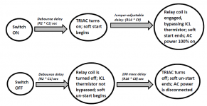
Figure 5 illustrates the sequence of events that occur when the equipment is turned On, and when the equipment is turned Off. As you can see, all delays are set by RC timeconstants on the PCB. Ambitious, self-confident DIY builders can modify these timeconstants, if desired, simply by changing component values.
INRUSH CURRENT: BEFORE AND AFTER INSTALLING SOFT START
Figure 2 is the "before" measurement; it shows a stereo chip amp's power on event with no soft start applied. Figures 6 and 7 show the same amplifier, but with this PCB installed between the transformer primary and the AC mains.
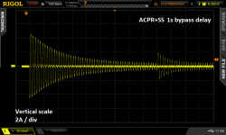
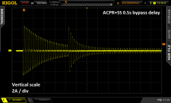
In both Figure 6 and Figure 7, the inrush current has been reduced quite dramatically. "Before", with no soft start (Figure 2), inrush current peak was 24 amps. "After", with this PCB installed, inrush current peak was only 4.4 amps (2.2 vertical divisions X 2 Amps / div). (The horizontal scale is 100 msec / div as reported at top left in the Figures.)
In Figure 6, a shorting bar has been connected on header P7 from pin 1 to pin 2. This selects the "0.5 second delay" option for ICL bypass. You can see that when the ICL is bypassed, AC mains current jumps up. Because there is suddenly less total resistance in the transformer primary circuit.
In Figure 7, the shorting bar has been moved to pins 3 and 4 of header P7, which selects the "1.0 second delay" option for ICL bypass. Now the bypass comes later, and the up-jump of AC mains current is smaller.
These figures suggest, at least to me, that a setting of 1.0 second delay before bypass is desirable. And that's what I'll be using in my equipment. But other DIYers have the freedom to choose other settings, as they see fit. Thank goodness the jumper select options permit this easily.
CAUTION: I PREFER MY LEDs VERY DIMLY LIT ; YOU MAY NOT
Resistors R3 and R4 set the current flowing in the power-is-on and/or the power-is-off LEDs. I chose quite large resistances for these because I like dimly lit LEDs. You may want to experiment with the LEDs you plan to use, and to discover the resistor values which give the LED brightness that you prefer, with 5V supply voltage. Do this before stuffing and soldering them into the PCB, of course.
(optional tech info): MORE ABOUT INRUSH LIMITER JOULE RATING
The Ametherm ICL I have recommended in the Parts List, is rated for 125 Joules. Is this too little? Too much? Just right? Let's look at a couple typical scenarios.
Example 1: a chipamp with plus/minus 36V supply rails, using a diyAudio Universal Power Supply, whose PCB has a total of eight electrolytic capacitors. Each capacitor is 15,000 microfarads with a 50V voltage rating. Four of these capacitors filter the +36V supply, and four of them filter the -36V supply.
The energy stored in each of the four V+ capacitors, is 0.5 * C * V * V. Plugging in numbers, (0.5 * 1.5E-2 * (+36) * (+36)) = 9.72 Joules. Since there are four V+ capacitors, that's a total of 39 Joules for V+
Similarly the energy stored in each of the four V- capacitors is 9.72 Joules. {why? because (+36) times (+36) equals (-36) times (-36)} The total for V- is also 39 Joules.
Adding them together, the total energy stored in the PSU is 78 Joules. Which is comfortably below the 125J rating of the Ametherm ICL.
Example 2: the AB100 amplifier by Nelson Pass. This is a 100W/ch class AB amplifier with plus/minus 55V supply rails. Each rail has two electrolytic capacitors rated 10,000 microfarads and 63 WVDC. For each capacitor, E = 0.5 * C * V * V = 15.2 Joules. Since there are four capacitors, the total is 61 Joules. Comfortably below the 125J rating of the Ametherm ICL.
Although it's not written in the official published specifications on the seller's website, I have read here on diyAudio that the Intelligent Soft Start board from Neurochrome Audio, allows 250 Joules of inrush current energy (!!). Twice as much as the 125 Joules of this PCB. DIYers who believe they need more than 125 J (but less than 250 J) of inrush current energy, should consider the Neurochrome board to be a good possibility.
SUMMARY OF PCB CHARACTERISTICS \ FEATURES
AVAILABILITY
I have attached the Gerber CAD manufacturing files for this PCB; its unique identifier is H9KPXG . The suffix "-C" indicates revision C of the layout. Anyone can send the .zip archive of these Gerber files to a PCB fab and have boards made; the design is public domain and uncopyrighted. Use them however you wish. I hope if you end up with extra PCBs, you will consider giving them away for free, or selling them at low cost, to other diyAudio members.
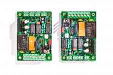
I strongly recommend that you have these built using BOTH 2-ounce-copper {double thick} traces, and also ENIG {gold} finish on the pads. An example is shown in Figure 8.
As of today, 23 May 2020, I have about twenty extra boards (2oz, ENIG) which I am willing to sell at my cost: USD 3.50 plus postage. One board per customer. In the present conditions I will be shipping to US addresses only. The required US Customs paperwork and face-to-face handoff for international shipments is, I regret to say, unacceptable to me. If you live outside the US and want a PCB, send these Gerber files to a PCB fab and have them ship boards straight to you. Give away or sell any extras.
A parts list is attached below. If a diyAudio member wants to turn it into a Shared Shopping Cart at Mouser.com, please go ahead with my best wishes. Just remember that 115V builders need one ICL part# while 230V builders need a different ICL part#.
_
Front panel switches with a circular pushbutton and colored illumination looked promising; the type called "Anti-Vandal" appealed to me. Figure 1 shows a few examples of them. UNFORTUNATELY, most of these switches are rated for low current DC applications like soda vending machines; very few are rated for AC mains switching at the high currents needed by power amplifiers. Worse yet, the inrush current that flows through the On-Off switch at the instant when the gear is turned on, can be enormous. Far too high for a switch rated 2A @ 24VDC. Figure 2 shows the measured AC mains current which flows, when a rather modest chipamp-based power amp (photo) is turned on. The inrush current peak is 24 amperes: (2.4 vertical div X 10 Amps per div). That's quite a stress for everything in the AC mains current path, including the On-Off switch's contacts. And remember, this is not some super-amp behemoth from Krell; it's just an Antek 200VA toroid, two LM3886 amp channel boards, and a diyAudio Universal Power Supply PCB. Yet its inrush current is frighteningly large.
It seemed to me the only way to use the Anti-Vandal On-Off switches I liked, was to use them at low current & low voltage. They wouldn't directly switch the mains; instead they would merely control a separate big, robust, high-current and high-AC-voltage switch. Perhaps such as a mains rated relay or triac.
Regrettably, more than half of these Anti-Vandal switches are momentary pushbuttons; they don't have latch-in-position action like rocker switches or toggle switches. To use them on the front panel of a power amp, an electronic latch or flipflop would be needed, giving "push on, push off" behavior.
SMALL LIGHTWEIGHT FRONT PANEL SWITCHES
Nelson Pass's 1992 amplifier DIY project called A75 (class-A, 75W/ch) used a triac to switch the AC mains off and on. The triac was controlled by a small front panel switch. The circuit reduced switch current to single digit milliamps, but it did require a front panel switch that can withstand the full AC mains voltage (230V in many countries). Very few of the Anti-Vandal switches meet this requirement, unfortunately.
Canadian high-end power amp manufacturer Bryston used an always-on, micropower, low voltage DC supply for their front panel power switch. It fires a triac, and the triac switches the AC mains on and off.
Australian engineer and prolific DIY project creator Rod Elliott offers Project 166 which is a Push-On, Push-Off Mains Switch. It includes an always-on, micropower, 12V DC supply. This powers a logic flipflop circuit which is the memory element for the push-push function. The flipflop operates a 12V relay, whose hefty contacts switch the AC mains on and off.
INRUSH CURRENT LIMITING WITH BYPASS
The measured inrush current waveform in Figure 2 indicates to me that some type of inrush current limiting is certainly needed, no matter how beefy and robust an on-off relay or triac is used. I still want to avoid over-stress of the transformer, the mains fuse, the internal wiring, etc.
I decided to also include a bypass circuit, which completely removes the inrush current limiter a short time after power on, when mains current has settled down to its normal (non-inrush) condition. Both Douglas Self's textbook and also Bob Cordell's textbook recommend inrush bypass circuits, on their page numbers 633 and 459, respectively. Bypassing the ICL reduces its current to zero, so it cools down and becomes ready for the next power-on event (a so-called "hot restart"). Bypassing the ICL also reduces the voltage dropped across it (to zero), which can be significant when the rectifier current-peaks are large. See Cordell p.459 for more.
The basic idea of inrush current limiting with bypass is sketched in Figure 3. Switch "SW1" turns the amplifier On and Off. Series resistor "NTC" performs the function of inrush current limiting. It guarantees that mains current cannot possibly exceed (Vmains / R_NTC) even if the rest of the primary circuit is an ideal short circuit. Switch "K1" bypasses the inrush current limiter after the inrush event has completed and mains current is down to its normal levels.
Inrush limiters have been successfully deployed using (a) ordinary wirewound resistors [Self], and also (b) specialized Inrush Current Limiter components [Cordell]. I decided to use option (b), the special ICL components. They offer a degree of extra safety in case the bypass mechanism fails open-circuit: an ICL can withstand the full primary current indefinitely. Whereas (a) wirewound resistors would self-destruct in less than one minute.
In construction, ICLs are enormous Negative Temperature Coefficient thermistors; a famous example is the CL-60, whose very part number includes CL for Current Limiter. I prefer not to refer to these as thermistors, to avoid confusion with the tiny little temperature sensors that also happen to have a negative temperature coefficient. So I will make an effort to always say "Inrush Current Limiter". Oh by the way, that happens to be the name that both Digikey and Mouser give to the section of their website where these components are sold. Forget Thermistor, remember Inrush Current Limiter.
When should the inrush limiting cease? When should the bypass turn on? Opinions vary. Texas Instruments bypasses the ICL when the amplifier's DC power rails have ramped up to approx. 60% of their final voltage (Fig.5 on p.7). Self suggests bypassing 1 second after power-on (p. 632). Rod Elliott's inrush current limiter for power amps, Project 39, enables the bypass after 0.1 seconds. A brief and incomplete survey of diyAudio discussion threads, turns up recommendations varying between 10 full cycles of the AC mains (0.2 sec) and 100 cycles of the mains (2.0 sec). All of this suggests to me that there are probably more than one right answer, and maybe the shrewd decision is to provide a few user-selectable options. As has previously been done in the Soft As A Feather Pillow soft start design by diyAudio members jhofland and xrk971, I chose the convenient 2X-per-step settings 0.5 sec, 1.0 sec, 2.0 sec. Thus bypass happens either 0.5, 1.0, or 2.0 seconds after power on, selected by a jumper on the PCB.
CIRCUIT SCHEMATIC DIAGRAM
Figure 4 is the schematic of this PCB. The power handling "business end" of the circuit in on the bottom half of the page; the top half is merely timing and LED management.
The actual front panel switch connects at top left; it switches only 5V DC at 0.5 milliamperes. This ripples through some digital logic gates and produces a digital signal "TRIAC_B", which turns on triac T1 through opto isolator U4. When T1 turns on, it applies mains power to the transformer primary windings. Notice that triac T1 is series connected with an Inrush Current Limiter device, "ICL1".
Component ICL1 a 22mm diameter device made by Ametherm, whose surge energy rating is 125 Joules. For 115V applications I recommend part number SL22-20007, whose cold resistance is 20 ohms and whose max continuous current is 7 amps. Thus the inrush current when the ICL is at room temperature, cannot exceed (115 / 20) = 5.8 amps, and that assumes the transformer primary, mains fuse, and AC wiring all add up to 0.00 ohms of additional resistance. [For 230V applications I recommend the SL22-50004, whose cold resistance is 50 ohms and whose max continuous current is 4 amps.]
After a user-selected delay time (chosen by setting a jumper across one of 3 sets of pins on header P7), the inrush current limiting is bypassed. Digital logic signal BYPASS turns on MOSFET Q4, which energizes the relay RL1 and shorts out the (triac + ICL) devices. Now there is no extra resistance inserted; the transformer primary is connected directly to the AC mains.
The relay, the indicator LEDs, and all of the digital logic are powered from a tiny AC-to-DC converter module, U2. Today these are available which meet the sub-0.5W international requirements for standby power, and they are delightfully small and cheap. The big electronics distributors carry modules made by RECOM, Mean Well, CUI, and TDK-Lambda. However the TDK modules are quite expensive (3X!), and the CUI modules are in stock at DigiKey but not Mouser. Since Mean Well appears to have by far the greatest number units in stock and on the shelf at Mouser, that's the one I selected. Eventually I settled upon a 5V model, after realizing (a) 12V relay coils don't consume any less power than 5V relay coils; and (b) LED circuits actually do consume more power when operated from a 12V supply than from 5V. It's only obvious in retrospect. And that's why the board uses CD4000 logic chips -- they work at 12V (and 5V, and 3V, and 18V)
The AC/DC module output is made available at connector P5, in case other circuits within the chassis may need a low voltage housekeeping supply. For example, a "breathing" style LED. I strongly urge you not to connect either of the housekeeping supply terminals (5V_HOT, 5V_COLD) to the ground pin of other circuits. Treat it as its own, self-contained, floating 5V supply. If interfaces are required, use optoisolators between circuits connected to the housekeeping supply, and audio circuits connected to audio ground. That way you cannot pollute audio ground with noise or garbage from the AC-to-DC module. The module is rated for 400mA but I recommend drawing less than 300mA from the P5 connector, to avoid overload.
To soothe my paranoia about electric shock, I've included a 25 ampere bridge rectifier "BR1" between 5V_COLD and chassis protective earth. Now in the very unlikely event that the (class 2!!) AC/DC module develops a short between AC mains LINE and DC output Minus, the mains voltage is shunted straight to protective earth through a very high current pathway: BR1. Even if somebody had connected 5V_COLD to circuit ground, against my recommendations, it still gets clamped to a non-dangerous voltage through BR1.
A couple more details about the circuits connected to the front panel switch. Firstly, a very long debouncing time is conservatively applied (using resistor R2 and capacitor C1), compared to the measured timings of typical switch-bounce events, as reported in The Ganssle Group's debouncing article. After that, a Schmitt trigger (U3A) adds hysteresis. These two mechanisms filter out and remove switch bounces very effectively, and present clean square waves to the downstream logic. Secondly, flipflop U1B is a memory element which remembers the current logical state (am I on, or am I off?) when the front panel switch is a momentary contact device. The PCB user installs a shorting bar across pin header P6 when using a momentary switch on the front panel; this enables U1B. If there is no shorting bar across P6, U1B is disconnected and the non-momentary front panel switch controls On-Off behavior and timing.
STATE TRANSITION DIAGRAM \ TIMING DIAGRAM
Figure 5 illustrates the sequence of events that occur when the equipment is turned On, and when the equipment is turned Off. As you can see, all delays are set by RC timeconstants on the PCB. Ambitious, self-confident DIY builders can modify these timeconstants, if desired, simply by changing component values.
INRUSH CURRENT: BEFORE AND AFTER INSTALLING SOFT START
Figure 2 is the "before" measurement; it shows a stereo chip amp's power on event with no soft start applied. Figures 6 and 7 show the same amplifier, but with this PCB installed between the transformer primary and the AC mains.
In both Figure 6 and Figure 7, the inrush current has been reduced quite dramatically. "Before", with no soft start (Figure 2), inrush current peak was 24 amps. "After", with this PCB installed, inrush current peak was only 4.4 amps (2.2 vertical divisions X 2 Amps / div). (The horizontal scale is 100 msec / div as reported at top left in the Figures.)
In Figure 6, a shorting bar has been connected on header P7 from pin 1 to pin 2. This selects the "0.5 second delay" option for ICL bypass. You can see that when the ICL is bypassed, AC mains current jumps up. Because there is suddenly less total resistance in the transformer primary circuit.
In Figure 7, the shorting bar has been moved to pins 3 and 4 of header P7, which selects the "1.0 second delay" option for ICL bypass. Now the bypass comes later, and the up-jump of AC mains current is smaller.
These figures suggest, at least to me, that a setting of 1.0 second delay before bypass is desirable. And that's what I'll be using in my equipment. But other DIYers have the freedom to choose other settings, as they see fit. Thank goodness the jumper select options permit this easily.
CAUTION: I PREFER MY LEDs VERY DIMLY LIT ; YOU MAY NOT
Resistors R3 and R4 set the current flowing in the power-is-on and/or the power-is-off LEDs. I chose quite large resistances for these because I like dimly lit LEDs. You may want to experiment with the LEDs you plan to use, and to discover the resistor values which give the LED brightness that you prefer, with 5V supply voltage. Do this before stuffing and soldering them into the PCB, of course.
(optional tech info): MORE ABOUT INRUSH LIMITER JOULE RATING
The Ametherm ICL I have recommended in the Parts List, is rated for 125 Joules. Is this too little? Too much? Just right? Let's look at a couple typical scenarios.
Example 1: a chipamp with plus/minus 36V supply rails, using a diyAudio Universal Power Supply, whose PCB has a total of eight electrolytic capacitors. Each capacitor is 15,000 microfarads with a 50V voltage rating. Four of these capacitors filter the +36V supply, and four of them filter the -36V supply.
The energy stored in each of the four V+ capacitors, is 0.5 * C * V * V. Plugging in numbers, (0.5 * 1.5E-2 * (+36) * (+36)) = 9.72 Joules. Since there are four V+ capacitors, that's a total of 39 Joules for V+
Similarly the energy stored in each of the four V- capacitors is 9.72 Joules. {why? because (+36) times (+36) equals (-36) times (-36)} The total for V- is also 39 Joules.
Adding them together, the total energy stored in the PSU is 78 Joules. Which is comfortably below the 125J rating of the Ametherm ICL.
Example 2: the AB100 amplifier by Nelson Pass. This is a 100W/ch class AB amplifier with plus/minus 55V supply rails. Each rail has two electrolytic capacitors rated 10,000 microfarads and 63 WVDC. For each capacitor, E = 0.5 * C * V * V = 15.2 Joules. Since there are four capacitors, the total is 61 Joules. Comfortably below the 125J rating of the Ametherm ICL.
Although it's not written in the official published specifications on the seller's website, I have read here on diyAudio that the Intelligent Soft Start board from Neurochrome Audio, allows 250 Joules of inrush current energy (!!). Twice as much as the 125 Joules of this PCB. DIYers who believe they need more than 125 J (but less than 250 J) of inrush current energy, should consider the Neurochrome board to be a good possibility.
SUMMARY OF PCB CHARACTERISTICS \ FEATURES
- Accepts low voltage, low current on-off switch
- Accepts either momentary action, or rocker-toggle action, switch
- Includes inrush current limiting ("soft start") with bypass
- User selectable delay between power-on and bypass
- Less than 0.5 watts standby power (when "power is now off" LED is omitted!)
- Housekeeping 5V DC supply provided
- 25A safety diodes between housekeeping supply and protective earth
- PCB mounting holes on 10 mm grid, matching Modushop perforated baseplate: Holes 60 x 90, edges 72 x 102 mm
- 125 Joules max inrush energy
AVAILABILITY
I have attached the Gerber CAD manufacturing files for this PCB; its unique identifier is H9KPXG . The suffix "-C" indicates revision C of the layout. Anyone can send the .zip archive of these Gerber files to a PCB fab and have boards made; the design is public domain and uncopyrighted. Use them however you wish. I hope if you end up with extra PCBs, you will consider giving them away for free, or selling them at low cost, to other diyAudio members.
I strongly recommend that you have these built using BOTH 2-ounce-copper {double thick} traces, and also ENIG {gold} finish on the pads. An example is shown in Figure 8.
As of today, 23 May 2020, I have about twenty extra boards (2oz, ENIG) which I am willing to sell at my cost: USD 3.50 plus postage. One board per customer. In the present conditions I will be shipping to US addresses only. The required US Customs paperwork and face-to-face handoff for international shipments is, I regret to say, unacceptable to me. If you live outside the US and want a PCB, send these Gerber files to a PCB fab and have them ship boards straight to you. Give away or sell any extras.
A parts list is attached below. If a diyAudio member wants to turn it into a Shared Shopping Cart at Mouser.com, please go ahead with my best wishes. Just remember that 115V builders need one ICL part# while 230V builders need a different ICL part#.
_
Attachments
-
 AV_switches_all.jpg278.9 KB · Views: 9,285
 -
H9KPXG_AC_mains_relay_SS_revC.zip95.8 KB · Views: 1,341
-
Parts_List_ACPR_SS.zip8.5 KB · Views: 1,203
-
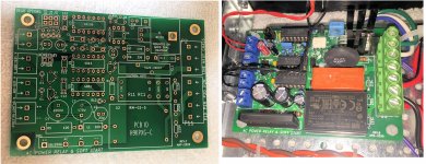 BOTH_BOARD_SHOTS.jpg844.7 KB · Views: 4,821
 -
 with_ACPRSS_1p0_sec.png49.8 KB · Views: 4,126
 -
 with_ACPRSS_0p5_sec.png50.4 KB · Views: 4,026
 -
 diagram_of_SS_timing.png66.6 KB · Views: 8,851
 -
 schematic_ACPRSS.png35.5 KB · Views: 9,032
 -
 Cordell_softstart_schematic.jpg101.3 KB · Views: 8,883
 -
 No_ACPRSS.png34.4 KB · Views: 8,087
Last edited:
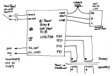
Couldn't quite attach all relevant figures to post #1. This last figure shows how to connect the AC mains relay & soft start board within a power amp.
This board assumes the amplifier's mains wiring includes a fuse, most likely incorporated into an IEC mains inlet module. One of these is drawn at upper right. The three output terminals of the IEC module are Earth (center), Neutral (left), and Line (right). Neutral and Line are wired to the AC Power Relay & Soft Start board (abbreviated ACPR&SS from now on). Earth is wired to the equipment chassis. On the same chassis bolt, another wire connects to the "Chas" terminal of the ACPR&SS.
The power transformer has two primaries. Primary number one is labeled P1 and primary number two is labeled P2.
The two wires of primary number one are further distinguished; one of them has a Phase Dot (check the transformer manufacturer's documentation) and the other does not. The primary one wire WITH the phase dot is named "P1D" and its name is spoken "Primary One Dot". The primary one wire WITHOUT the phase dot is named "P1N" and its name is spoken "Primary One NoDot". Same for primary number two.
On the Antek AS-2222, for example, P1D is a red wire and P1N is a black wire. Similarly, P2D is a red wire and P2N is a black wire. Check your transformer documentation to find out which wires do, and do not, have phase dots. Make careful notes of their colors.
The On-Off switch connects to the ACPR&SS at upper left. Since this is a low voltage, low current circuit, just about any wire type will suffice. 26 AWG stranded wire, for example, is perfectly acceptable. The connections to the PCB are unchanged, whether you use a momentary pushbutton switch or a rocker-toggle action switch. (That is handled by an electrical jumper "P6" on the board).
_
Attachments
Here's a Mouser cart (I think I did this right?)—115V version:
Mouser Electronics
Thanks for this project Mark!
Mouser Electronics
Thanks for this project Mark!
Wow! Thank you, Patrick, that is amazingly generous of you.
If at some future date, you discover a need or reason to revise the cart, let me gently suggest revising the quantity on one line item. Buy five or ten of the Kycon SX1100-B jumpity jumper units. Users will need one for the delay option and perhaps one more for the momentary-switch option. But why not get a few extra, since they are so easy to misplace (and so cheap to buy). Sorry that my PartsList has qty=1 , thus is misleading. I'll put it on the list of edits-to-make.
If at some future date, you discover a need or reason to revise the cart, let me gently suggest revising the quantity on one line item. Buy five or ten of the Kycon SX1100-B jumpity jumper units. Users will need one for the delay option and perhaps one more for the momentary-switch option. But why not get a few extra, since they are so easy to misplace (and so cheap to buy). Sorry that my PartsList has qty=1 , thus is misleading. I'll put it on the list of edits-to-make.
Wow! Thank you, Patrick, that is amazingly generous of you.
If at some future date, you discover a need or reason to revise the cart, let me gently suggest revising the quantity on one line item. Buy five or ten of the Kycon SX1100-B jumpity jumper units. Users will need one for the delay option and perhaps one more for the momentary-switch option. But why not get a few extra, since they are so easy to misplace (and so cheap to buy). Sorry that my PartsList has qty=1 , thus is misleading. I'll put it on the list of edits-to-make.
SURE!
Your parts list had "10" for the jumper...for some reason it didn't stick when I made the project.
Here's an updated link:
Mouser Electronics
I ordered some boards from a PCB fab, first time doing that—we shall see—I need more than your limit of 1—M2X mono blocks. My mounting options are limited—hopefully the amps stay quiet... I'll try one and see.
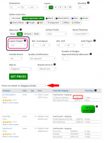
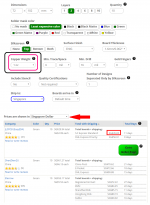
I would ONLY use 1 oz copper (35 micron thickness) on the PCB, if I was absolutely certain that the mains transformer's Volt-Ampere rating was less than 201 VA. If the transformer was any bigger than that, I'd insist upon 2 oz copper.
Besides, the price difference between 1 ounce and 2 ounce copper, isn't very big. Here is what PCBShopper – A Price Comparison Site for Printed Circuit Boards has to say:
+
Besides, the price difference between 1 ounce and 2 ounce copper, isn't very big. Here is what PCBShopper – A Price Comparison Site for Printed Circuit Boards has to say:
+
Attachments
Hi Mark,
Nice compact project. Have done something similar a while back, also with a ring-LED Push button switch (Black with White led).
I’ve added a childproof feature: you have to keep the push button pressed for about 4seconds before the amp switches on. Have two kids from 5 and 7 years old!
https://www.diyaudio.com/forums/sol...low-nfb-fet-front-bjt-ops-13.html#post6043036
Switch: Anodized Aluminium Push Button with White Circle Light 1NO1NC 250V 5A O25mm Black - Audiophonics
I’ve added a childproof feature: you have to keep the push button pressed for about 4seconds before the amp switches on. Have two kids from 5 and 7 years old!
Hi Bensen, thanks for the links! Your mains relay + soft start board looks extremely nice. The childproof feature of loooooooooong press to turn on, is a great idea, congratulations! Although in my experience, lots of kids are extremely shrewd and if they see Pops pressing the super neato button for a long time, they'll very likely do the same thing.....
Hi Brian, thanks for your input! I haven't met very many people who are enthusiastic proponents of external triggered on/off control. Would you mind saying whether you're actually using it today, in your everyday setup? Or are you thinking about PCB features that might be useful to others? Or useful to yourself, one day in the possible future?
Hi Mark, i am not using it now - but i want to ")
I am listening to Roon via an always on raspberry pi. What i am working towards, is using a GPIO from the rPi to trigger the DAC, and then the rest of the chain. A while back i started designing a PCB which, apart from the functionality on your PCB, has trigger in/out (with apropriate trigger out delay) and loss of AC detection (for speaker relays). However i have way to many projects, and with your well engineered PCBs, i am one step closer to finishing my F6
I will propably have three extra PCBs in Denmark, if anyone is interested.
I use this for low voltage on off...
What does yours do that this doesn't since I assume it will cost more than 3$ to build it...
12V Bond Bistable Relay Module Car Modification Switch Start Stop Self-Locking | eBay
EDIT: Yours does soft start, this one doesn't. Not sure how I missed that, but since I was using a 120V switch with no soft start before it made no difference. When I need soft start, it's accomplished with a time delay relay that shorts a 500R 20W resistor.
By the way, if anyone wants to make before-and-after photos of inrush current, with and without countermeasures (this board, a different board, etc.), maybe the little homebrew test fixture I built a couple years ago might be a useful starting point. A circuit schematic and photo of working fixture are in post #41 here. If that link isn't working the post date was 16th Dec 2018.
I used the MOC3063M optocoupler and the BT139 triac back then; they worked well for me and the cost was low. So I used the same parts again, in this AC power relay board; they're known good.
Notice the double dose of conservatism in post #41: galvanically isolated, battery powered switch, AND gloves. With good result: many tests but zero electric shocks to the operator (me).
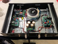
Here is an example of the AC power relay board, mounted on the 10 x 10mm grid of a Modushop chassis baseplate. This PCB is the one indicated by a yellow arrow on the photograph.
For the front panel switch, I used a 19mm diameter, illuminated pushbutton that I bought from Newark (link)
_
For the front panel switch, I used a 19mm diameter, illuminated pushbutton that I bought from Newark (link)
_
Attachments

Thank you very much!
If you're thinking of doing your own board, please also have a look at the design by member Bensen (links in post #8) for additional ideas. Plus of course, the original sources linked in post #1: Pass, Elliott, Cordell, Self, jhofland, T.I., Bryston, Ganssle et. al. Between all of them you'll get a bunch of ideas and a bunch of already-proven subcircuit blocks, which you can mix and match and tweak and fiddle, however you please.
If you're thinking of doing your own board, please also have a look at the design by member Bensen (links in post #8) for additional ideas. Plus of course, the original sources linked in post #1: Pass, Elliott, Cordell, Self, jhofland, T.I., Bryston, Ganssle et. al. Between all of them you'll get a bunch of ideas and a bunch of already-proven subcircuit blocks, which you can mix and match and tweak and fiddle, however you please.
I just made up a couple of these boards.. Thanks Mark!!
Found an error in my cart!!—fixed here:
Mouser Electronics
I'll post some pics of the built boards later...
Suffice it to say I learned a lot about soldering—and I wouldn't say I'm a novice there—but I had to go up 100 degrees F to get some areas to flow... Assuming that's due to the fact that more than half the board is copper...? The experience was the same for both boards... Kinda interesting...
- Home
- Amplifiers
- Power Supplies
- PCB: low voltage On-Off switch drives AC mains relay \ includes soft start .. H9KPXG