Thank you; I will add these to the list of requested new features.
Hi Mark, I see that the L an N input and transformer connection block then (ideally) should be swapped. Aesthetical as it prevents crossing wiring and wire routing is nicer when the PCB is used with an IEC inlet at the right side of the back cover. The SMPS is then also most far away from sensitive circuits just like the transformer and all mains related wiring.
And eh... the timer could also switch a speaker relay (in 2020 this is a revolution in audioland I experienced
") ) maybe even after the same delay as the loudest plop is straight at power on...... just 1 heavy duty relay, an extra connector, a few parts extra and it is a complete power on/off solution for amplifiers. DC protection is not debatable in this day and age and is considered old fashioned so it can be omitted. Plopless power on/off is a true enhancement of the user experience of a DIY amplifier although some seem to enjoy it depending on who designed the device.
) maybe even after the same delay as the loudest plop is straight at power on...... just 1 heavy duty relay, an extra connector, a few parts extra and it is a complete power on/off solution for amplifiers. DC protection is not debatable in this day and age and is considered old fashioned so it can be omitted. Plopless power on/off is a true enhancement of the user experience of a DIY amplifier although some seem to enjoy it depending on who designed the device. If the speaker relay footprint also includes pads for an external small signal relay Molex KK connector (so muting relay off board) people can use the board for preamp/input/source muting too.
Last edited:
Jean-Paul, if those modifications / improvements are really important to you, please accept my blessings and invitation to re-layout the board yourself, incorporating those and whichever other tweaks you deem beneficial. It would not hurt my feelings at all, in fact it would be a little flattering, and I wish you robust success on the very first try. Since I am presenting PCB Rev.C here, you can see that I did not have complete success on MY first try
If these improvements are really important to you, please consider: you have no way to predict or even to guess, how long the waiting time will be until I release a new revision. You have no way to predict or guess whether my next PCB revision will include none of your suggestions, some of your suggestions, or all of your suggestions. [and in fact neither do I. I honestly have no idea.]
Doing the revision yourself, or supervising an employee who does the revision, removes all guesswork. You know the schedule and you know the set of incorporated features, with great confidence. Waiting is minimized and doubt is eradicated. This would bring enormous peace of mind, if the modifications are really important to you.
It’s just audio right?
Seems unwarranted given that the op has provided constant input and support to his great design.
Thanks again Mark for all of your work on this!
I could not care less really. Just suggestions which might give possibilities for extra functionality/versatility which I would include. For others that is, there is no interest of me in the device so no personal gain or something like that. I can design and build such a device and design a PCB. It just costs time. Thought you would be open to suggestions to improve it as you gave that impression but apparently you are a somewhat bitter person considering the quite cynical and unpleasant attitude.
Seems unwarranted given that the op has provided constant input and support to his great design.
Thanks again Mark for all of your work on this!
Mark,
Thank you!
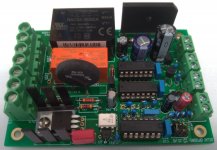
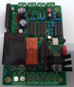
I ordered PCBs based on your design data (first experience for me) and completed two today.
I will use these for mono block singing bush power amps.
Let me ask you one question.
The board seems to work fine when I load (light bulb as a test) the P1D/N terminals.
When the mini switch is Off, there is no AC voltage on P1D/N. When the switch is turned on, AC100v will come to P1D/N.
However, when P1D/N is open (no load), AC 100v is measured by the DMM regardless of whether the switch is On or Off.
The two I made have the same behavior.
Is this normal?
Thank you again.
Thank you!
I ordered PCBs based on your design data (first experience for me) and completed two today.
I will use these for mono block singing bush power amps.
Let me ask you one question.
The board seems to work fine when I load (light bulb as a test) the P1D/N terminals.
When the mini switch is Off, there is no AC voltage on P1D/N. When the switch is turned on, AC100v will come to P1D/N.
However, when P1D/N is open (no load), AC 100v is measured by the DMM regardless of whether the switch is On or Off.
The two I made have the same behavior.
Is this normal?
Thank you again.
Attachments
Congratulations on your success, yoshida! Your assembly and soldering appears to be first class. I hope you are quite pleased with the finished equipment.
It's true that modern, very high impedance voltmeters read non-zero voltages on the "transformer primary" output terminals, even when the triac is off. Other builders have noticed this, see posts #65 and #66 in this thread for example.
You can prove to yourself that the voltmeter reading is nothing to worry about, by temporarily connecting a 100K resistor across the voltmeter probes when performing the measurement. Presto, the voltmeter reading immediately falls to zero. Another experiment you can try, is to connect a very low wattage, mains-powered incandescent light bulb where the transformer primary would go. A bathroom night-light (3W in USA) would be perfect. Presto, the bulb does not light.
Thank you for reply. And, I'm sorry for my lack of study.
Now I can use the board with confidence.
And I distribute the extra PCBs to DIYer in Japan.
This was manufactured by JLCPCB based on mark's data.
Surface Finish is HASL (with lead). It is not ENIG finish.
Copper Weight is 2 oz.
I paid $35 for 10. So, I distribute 1 for 500 yen including shipping.
Please PM if you interested.
Thank you again.
Yoshida, this is wonderful! It makes me so happy!
I am thrilled when diyAudio members make a new and brave step, to order PCBs! Congratulations on your attempt and, double congratulations upon your success! You were brave, you performed an action, and you were victorious. Well done!
Also: blessings + good wishes that other members will be interested in buying your left-over boards. You Da Man! as they say in American sports magazines. Other members are very grateful for your efforts!!
Hi Mark,
Thanks for sharing this with us. I have soldered up the board and am ready to connect it up to the transformer.
A quick question: This is probably quite straightforward but I’m new to this and want to be clear when dealing with mains electricity! I have the 230V jumper connected (I’m in the UK) – my transformer has only one primary, how do I connect it to this board?
Best wishes,
Michael
Dear pinnocchio, congratulations and Good On Ya! I'm glad you decided to order some PCBs and succeeded in the endeavor. It takes bravery to try new things!
I've got plenty of these PCBs in my private storeroom, but if you'd like to sell off your extras to other diyAudio members at a small profit (or at breakeven, zero-profit), I'm sure they would be very grateful.
Well done,
Mark
I've got plenty of these PCBs in my private storeroom, but if you'd like to sell off your extras to other diyAudio members at a small profit (or at breakeven, zero-profit), I'm sure they would be very grateful.
Well done,
Mark

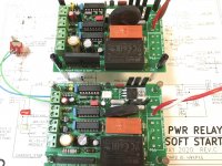
Hello everyone
I wanted to thank Mark Johnson for his generosity in sharing this project and saying that I was one more who decided to follow Mark Johnson's recommendation, and ordering PCB's (for the first time) to do this project.
Below is a pair of photos from my finished and verified soft start.
The pcb was ordered according to all indications provided by Mark Johnson, and it is working as expected, except for one point, and this is what puzzles me. If I don't connect anything to P1D; P1N and P2D; P2N, I can measure 230v at the output terminals. If I connect the 30VA toroidal that is intended for a Nelson Pass BA-3 preamp, I have no reading on that terminal but I have it in P2D; P2N. Changing the connections (P1 to P2), the same happens, I get reading in P1 and zero in P2 ...
If you bypass the toroidal connection to the soft start, I will have + - 24V on the power regulation pcb again.
I would appreciate some guidance, I am doing something wrong, I have something badly connected, whatever ...
Thanks in advance.
Best regards
Carlos
Attachments
Last edited:
Sketch is connection for one transformer with two primaries. You have one primary.. If you have connected both transformers, remove them and measure again to confirm you only have 230V between P1D and P2N. If you are measuring both transformers connected then they are in series, but I can't help you if this is right way to connect two transformers to one board because I am very new to this DIY audio stuf and have no clue how would connecting two transformers in series affect your amplifier.
Last edited:
- Home
- Amplifiers
- Power Supplies
- PCB: low voltage On-Off switch drives AC mains relay \ includes soft start .. H9KPXG