
I just wanted to point out something. I ordered these boards and noticed that the trace widths for Line in and transformer winding out are narrower than the traces on board REV C. Rev C looks to be double the width of D. D is 2mm wide.. I played around with the PCB trace calculator and seems like current capacity might be a bit low for large power amps even with 2oz of copper...I slightly reduced the size of the board so that you can order $5. Resistors and capacitors SMD 0805 and 1206.
In the archive, files for ordering boards at work.
Attachments
Just a note for other user that will read some previous post (from #632 to #639)I just wanted to point out something. I ordered these boards and noticed that the trace widths for Line in and transformer winding out are narrower than the traces on board REV C. Rev C looks to be double the width of D. D is 2mm wide.. I played around with the PCB trace calculator and seems like current capacity might be a bit low for large power amps even with 2oz of copper...
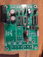
The board to which @Joel Wesseling is referring is not the original Mark Johnson layout of the board and is marked as rev D. This rev D. board use some SMD resistors and a different AC/DC converter module.
This rev. D board can accept the Hi-Link HLK-5M05 AC/DC module but not the one on the original BOM because different pin out.
Just to be very clear, I've nothing to say about this rev. D board, only point out this little difference that can confuse some other users.
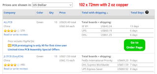
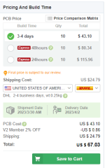
Original PCB laid out by me is 102 x 72 mm, here are current price quotes from www.pcbshopper.com. Notice that the price quote is for quantity = 10 PCBs.
_
_
Attachments
I saw something a couple pages back, but better to check directly with @Yurik_VThanks mvaldes, I was a confused one🤪
Where is the link to rev. D? I’d like to check out the differences between C and D?
Gerber Rev. D
https://www.pcbway.com/project/shar...mains_relay_includes_soft_start_2e05ee9f.html
1 oz is $5 for 10
2 oz is $43 for 10
1 oz is $5 for 10
2 oz is $43 for 10
Attachments
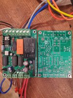
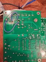
I built 2 revision D boards. Everything looked fine at power up(primary windings connected) but when the on switch was closed the relay was turning on and off. The 5V supply would drop to zero volts, then back to 5V, then back to zero continuously.
After hours of investigation, looking(unsuccessfully)for something that I might have done incorrectly during assembly I began examining the traces.
Turns out that the 5V psu has the supply line trace on both AC pins.
Made some changes on the bottom to cut the hot and connect the neutral. The boards now operate correctly
Attachments
The board to which @Joel Wesseling is referring is not the original Mark Johnson layout of the board and is marked as rev D. This rev D. board use some SMD resistors and a different AC/DC converter module.
This rev. D board can accept the Hi-Link HLK-5M05 AC/DC module but not the one on the original BOM because different pin out.
I am sure everyone is disappointed to learn that the rev D. PCB from @Yurik_V contains a connection error. Fortunately, the rev C board that I describe in post #1 of this thread, was run through the "Electrical Rules Check" and the "Layout Versus Schematics Check" programs within KiCad, and passed with no error flags. The rev C board does not contain this mistake.
- Home
- Amplifiers
- Power Supplies
- PCB: low voltage On-Off switch drives AC mains relay \ includes soft start .. H9KPXG