Lovely work, @richb, congratulations! It's a fine looking board and the slanty wavy heatsinks are a nice touch.
If you are in the mood for thenever-ending hellish nightmare exciting and fulfilling experience called "customer support", you could start a new thread which discusses the unique characteristics of your board, and which includes Gerber files so that others may send it to PCB fab. I suggest you emphasize the remote control feature heavily, very few others offer that possibility.
If you are in the mood for the
Thanks Mark. The heatsinks (AAVID TV5G) were just what I could easily get in roughly the right spec from my usual suppliers here in the UK.Lovely work, @richb, congratulations! It's a fine looking board and the slanty wavy heatsinks are a nice touch.
If you are in the mood for thenever-ending hellish nightmareexciting and fulfilling experience called "customer support", you could start a new thread which discusses the unique characteristics of your board, and which includes Gerber files so that others may send it to PCB fab. I suggest you emphasize the remote control feature heavily, very few others offer that possibility.
I'll work up the courage to branch a thread for this development when I'm happy with a reference firmware.
The circuit assumes that the always-on, 5V DC power supply (baby switcher) is always on.
However, when the power cord is first plugged in, that assumption is false, and the circuit's behavior is undefined. It takes a few seconds for the baby SMPS to wake up and reliably produce 5V output; but while the 5V supply isn't 5V, behavior is undefined.
However, when the power cord is first plugged in, that assumption is false, and the circuit's behavior is undefined. It takes a few seconds for the baby SMPS to wake up and reliably produce 5V output; but while the 5V supply isn't 5V, behavior is undefined.
Some ideas:
- Using a SMPS instead of a linear power supply reduce inrush current because the filter capacitors are more smaller (capacitor is a short-circuit when PS starting so reduced input capacitors reduces the inrush current). By using a linear regulator after the SMPS you can reach a clean power supply for audio circuits. Of course, it is more easier for small currents (as in a preamplifier). For a power amp, it is more difficult to using a linear regulator but it is possible. Use a LDO (Low drop out regulator) to have less power dissipation. The LDO acts as an active filter
- APEM id one of the best switch and pushbutton manufacturer in the world (it is used in the planes, civil and military). for example, take a look at 600 series (15A @ 220Vac). For pushbutton, a way is not cutting directly 220Vac but control a relay or a triac. Of course, with this method you need an auxilary isolated power supply. For that I use a XP POWER ECE05 or equivalent (Meanwell, RECOM, have very little AC/DC PS at a cost < 10€).
- For inrush current, no idea on a AC line (maybe see some elektor articles). For DC line, use a eFuse (TI or MAXIM have such IC). With a eFuse, you can control the ramp of the output voltage (just with a little capacitor in the nF range). Moreover, with a eFuse, don't need any replacement when an overcurrent happens (auto-recovery mode, ...).
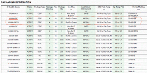
Hi All.. Working on putting a parts order in for a few of these boards.. Ran into a problem finding CD4001BEE4 (U5). Used the 'compare similar' feature on Mouser and they came up with this substitute.. CD4001BE.. Anyone know if this will work as a substitute? Thanks much!
https://www.mouser.com/ProductDetail/Texas-Instruments/CD4001BE?qs=Tv815z3GeNSKspfG7F34rg==
https://www.mouser.com/ProductDetail/Texas-Instruments/CD4001BE?qs=Tv815z3GeNSKspfG7F34rg==
The datasheets on both parts... regardless of Mouser's designations... are identical... Same exact file...
I think you are good.
Agree; but there can be multiple parts in one data file. In this one, I see 14 different "CD4001" parts. However I do not see the difference BE or BEE4.
These old-old parts, *usually* if you get the right CD40__ number and the right legs (ones you can solder), it will be fine.
Attachments
Agree; but there can be multiple parts in one data file. In this one, I see 14 different "CD4001" parts. However I do not see the difference BE or BEE4.
These old-old parts, *usually* if you get the right CD40__ number and the right legs (ones you can solder), it will be fine.
Thanks PRR, need to do some learning about data files.. amongst other things
Yes, a fair point I have no doubt.
I'm hoping that by sharing on this forum, projects are seen as 'here's a thing that is designed to do XYZ, feel free to reproduce or customise as you like', rather than as an offering of a bespoke service. Then it can be used as is, or built upon based on your own ideas and expertise.
For this board in particular, I have a software that mimics your original functionality except for being dual channel (as developed for my immediate need), and I can easily add some simple configuration for sequenced startup. Beyond that, it's open for experimentation, with resonable assistance of course. I hope I'm not being too naïve!
Ha ha. I was looking at a similar project, but using an off the shelf arduino board with relay shield. My use case is similar, daisy chaining with sequenced start up delay as I have 3 components (streamer, pre power) each with such a large psu that the inrush from any one of them will trip the mains. For 40 euro you can get an off the shelf solution for all the surface mount challenges, plus a development environment, plus a "fail safe" isolation to any high voltage circuits (via the relays)
What would be handy in that respect is certainly the high voltage part of the circuit, plus a simple interface for "third party" trigger logic via a board2wire header. Suspect you already have that if you're planning on using just one atmeg, and then daisy chaining.
But if you've already "solved" the daisy chaining with sequenced start up delay via atmeg I'd certainly be ok going that route too.
Would you be interested in a group buy of boards? I'd take 4.
Regards and thanks for sharing.
I'm assuming the inductor at L1 does not have a polarity. I read the data sheet (nothing about polarity) and searched some posts on the internet, which leads me to believe there is no polarity in a two lead inductor. I've never worked with an inductor like this before and what's holding me back is the the square pad on the PCB on one side of L1.
I've installed the resistors on the PCB, moving on to capacitors, so if no-one stops me soon I'm going to solder L1 home and not worry about the direction.
I've installed the resistors on the PCB, moving on to capacitors, so if no-one stops me soon I'm going to solder L1 home and not worry about the direction.
I'm no expert but I have been working through basic electronics chapter by chapter. Inductors do not have polarity. You are observant to have noticed the square. I don't know why it's there and I hope somebody explains why it's there. I have noticed it on other boards with non-polar parts like resistors every now and then. Maybe the layout program always puts a square pad on the positive side even if the part isn't polarized.
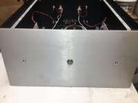
My amplifier previously had the two blue LED indicator lamps and now has a 19mm opening for an Anti-Vandal switch. My ambition is to have the switch ring lit green in "standby" mode and blue in the "on" mode with the two indicator lamps coming on as well, all powered by the H9KPXG.
I'm having a hard time finding a switch meeting my requirements:
Anti-Vandal
19mm
momentary
bi-color green/blue
common cathode
I've searched many manufacturer sites (Bulgin, E-Switch, etc.) but haven't come up with a solution yet.
I've also searched this thread and found an alternative wiring for using reverse bias diodes seen on many bi-color switches...that solution doesn't appeal to me. Audiobears bi-color solution had me excited but that switch is red/blue and 16mm.
Any Ideas would be appreciated?

- Home
- Amplifiers
- Power Supplies
- PCB: low voltage On-Off switch drives AC mains relay \ includes soft start .. H9KPXG


