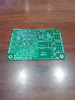
I have 5 PCB's available made with 2 oz spec. I have $9.56 my cost for each board with shipping from China.
I sent you the incorrect zip in my PM. Please check that message for correction. Should be 55419.
Thanks,
Ryan
For all those in Australia and New Zealand. I have 4 spare boards left over from my JLPCB order. No charge, just postage.
In answer to folks wanting to remotely switch the soft start circuit, I'm using my board in a Boss accoustimass subwoofer rebuild. I have selected a PC-817 optocoupler. The transistor is simply wired across the switch pins and the LED is driven via a suitable series resistor. I think this is probably better than using a relay. Plenty of schematic samples for driving the pc-817 on the interwebs.
Moz
Attachments

For those having trouble sourcing parts in Australia here's a few things that may help.
Rockby electronics stock the large mains side screw terminals.
A 2N7000 might work in place of the TN2106
Altronics Z0089 might do for the bridge rectifier but the pin pitch is a bit off.
I've had to import the relay and power module as I haven't found a local match yet
Rockby electronics stock the large mains side screw terminals.
A 2N7000 might work in place of the TN2106
Altronics Z0089 might do for the bridge rectifier but the pin pitch is a bit off.
I've had to import the relay and power module as I haven't found a local match yet
Thanks for the heads up.
According to TN2106N3-G Microchip - MOSFETs - Distributors, Price Comparison, and Datasheets | Octopart component search RS and element14 have stock of a TN2106.
Haven't checked but the other bits may be covered by the same route.
RS is good because they ship for no extra charge and do so as the receive components. They can be handy for those odds and ends you find you've missed in the final stages of a build.
Last edited:
Thank you to Mark for sharing this design, very useful.
This is something that I really should apply to a pair of Quad 405's that I run, which dim the house lights when turned on simultaneously! I'd previously toyed with an IR-controlled mains switch so I could have them turn on alongside the preamp, but never applied it.
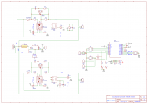
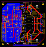
So in the spirit of customisation, I've taken this design and made a dual-output version, using a simple Arduino microcontroller to run the IR receiver, alongside replicating the state transitions and switch/jumper/LED interface, with the minor difference of using 2 delay selection jumpers to choose one of 4 possible delays (0.5, 1, 1.5 or 2s).
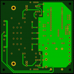
I'd like to get any comments on the PCB design before I send it to be manufactured. Size is 99x99mm (which gets it within the cheap prototype size limit of some fabs), with 90mm mounting hole spacing. I should have spare PCBs if there's any interest in this version, and can share the Gerber files too. Thanks
This is something that I really should apply to a pair of Quad 405's that I run, which dim the house lights when turned on simultaneously! I'd previously toyed with an IR-controlled mains switch so I could have them turn on alongside the preamp, but never applied it.
So in the spirit of customisation, I've taken this design and made a dual-output version, using a simple Arduino microcontroller to run the IR receiver, alongside replicating the state transitions and switch/jumper/LED interface, with the minor difference of using 2 delay selection jumpers to choose one of 4 possible delays (0.5, 1, 1.5 or 2s).
I'd like to get any comments on the PCB design before I send it to be manufactured. Size is 99x99mm (which gets it within the cheap prototype size limit of some fabs), with 90mm mounting hole spacing. I should have spare PCBs if there's any interest in this version, and can share the Gerber files too. Thanks
Attachments
Can anyone tell me the finished height of the board with all components installed including the PCB?
I would like to see if this would fit into my current build.
Thank you,
David.
My build with really BIG Inrush Current Limiter (tallest part on PCB) is 30 mm.
Can anyone tell me the finished height of the board with all components installed including the PCB?
I would like to see if this would fit into my current build.
Thank you,
David.
My build with the std inrush limiter (for 115V) and BR1 lifted a couple mm is 25mm.
Don't forget the space you need between the board and mounting surface. I use 6mm.
Don
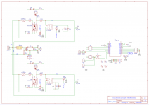
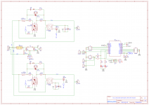
richb - great job, congratulations! I assume you have taken great pains with the two digital control signals from the microcontroller, which turn the triacs on and off. You want those signals to default to the +5 rail in times of uncertainty, like power-up and power-down and digital-supply-voltage-is-not-yet-all-the-way-up. You want those two discrete PMOS transistors (Q3A and Q3B in your schematic) OFF. OFF, OFF, OFF the f-word OFF. Even when the central processing unit is brain-dead and software is not running.
Since you are not constrained by the number of available unused gates in a CD4001 DIP-14, you can consider finagling the circuit so it uses discrete NMOS transistors (not PMOS anymore), to turn the triacs on and off. Now the two control signals should default to the GND rail in times of uncertainty. Maybe this is easier with an Arduino? (I have no idea)
On your pcb layout, it looks great. Just a couple of suggestions for possible extra polishing
1. How about one or two supply bypass capacitors above the Arduino module, next to "Pro Mini 5" ??
2. The low voltage signal on Q3A pin 1, gets awfully close to the high voltages (especially with 230V mains) used by the 6 pin opto-triac. Maybe you could slide Q3A and R11A to the left by 3mm or so. Also maybe you could slide R12A downward by a couple of mm.
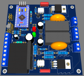
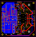
Here's the updated PCB.
As suggested:
- Triac switches changed from PMOS to NMOS; 'safety' pull-downs on triac and relay switch signals
- Re-routing and layer changes to improve low-voltage to high-voltage separation around Q3/R11/R12
- There is already supply decoupling cap C1 close to the Arduino VCC pin - should this be adequate?
Also:
- Created extra space and added extra hole in footprint to accommodate larger MS32 series alongside SL22 series NTC (as discussed earlier in this thread)
- Increased spare digital I/O brought to holes from 2 to 4
Attachments
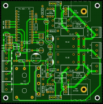
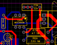
Very nicely done, richb! Super job. Do you think you could micro-optimize (nano-optimize?) the blue trace coming off U4 pin 2, so that it becomes a wee little ooch farther away from the red round hole on C3A? You might could get another 1/2 or 1mm distance after ten minutes' worth of fiddling. (??)
Hi richb, nice job. Time ago I've made a circuit with an embedded Atmel328 (I like to use the micro itself instead the whole Arduino) to have a correct power on sequence of my DIY system (DSP+digital xover+dual BII DAC+trigger for power amps) and I've have in mind to redesign it including also the soft start, but time is so little...
Mark gave you very precious suggestion and I would add also pull up resistor to on off switch.
You should consider also that Atmel 328 can easily drive the optocoupler so you can get rid of Q3 increasing the reliability of the system (less is better).
I'm sure Mark will tell you if this is fine or not
Thanks. Yes, good call, there seemed no reason not to push C3 right a little too, so this (shown below) will hopefully do.Very nicely done, richb! Super job. Do you think you could micro-optimize (nano-optimize?) the blue trace coming off U4 pin 2, so that it becomes a wee little ooch farther away from the red round hole on C3A? You might could get another 1/2 or 1mm distance after ten minutes' worth of fiddling. (??)
Hi richb, nice job. Time ago I've made a circuit with an embedded Atmel328 (I like to use the micro itself instead the whole Arduino) to have a correct power on sequence of my DIY system (DSP+digital xover+dual BII DAC+trigger for power amps) and I've have in mind to redesign it including also the soft start, but time is so little...
Mark gave you very precious suggestion and I would add also pull up resistor to on off switch.
You should consider also that Atmel 328 can easily drive the optocoupler so you can get rid of Q3 increasing the reliability of the system (less is better).
I'm sure Mark will tell you if this is fine or not
Thank you too. That sounds like a nice job you did there.
The switch input will be pulled up internally in the '328. This will happen well before the first detection of the switch level, so should be safe.
As for driving the optocoupler directly, as you say the the maximum activation current of 5mA (x2) is well within the '328 capability of 40mA, so this sounds like a good suggestion, many thanks for that.
Attachments
This was a pretty easy mod, here's how it would look.Hi richb, nice job. Time ago I've made a circuit with an embedded Atmel328 (I like to use the micro itself instead the whole Arduino) to have a correct power on sequence of my DIY system (DSP+digital xover+dual BII DAC+trigger for power amps) and I've have in mind to redesign it including also the soft start, but time is so little...
Mark gave you very precious suggestion and I would add also pull up resistor to on off switch.
You should consider also that Atmel 328 can easily drive the optocoupler so you can get rid of Q3 increasing the reliability of the system (less is better).
I'm sure Mark will tell you if this is fine or not
Attachments
- Home
- Amplifiers
- Power Supplies
- PCB: low voltage On-Off switch drives AC mains relay \ includes soft start .. H9KPXG