After reading Miketts experience of using one rail of this psu at 3v3 for AVCC on an ESS dac I thought I'd try one.
#Aliexpress £12.77 | HIFI DAC power supply Class A dual power supply multiple outputs Dual DC ± 12V ± 15V ± 18V Single 5V 3.3V H151
HIFI DAC power supply Class A dual power supply multiple outputs Dual DC +- 12V +- 15V +- 18V Single 5V 3.3V H151|Amplifier| - AliExpress
Space is at a premium in my streamer build using Ian c
Canada dac parts. I was feeding all 3 dac rails by LT1963 at 3v3 and IV stage was by Studer900 type at+/-15.
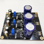
I ordered the above psu with 1 x 3v3 and dual 15. It is quite a bit smaller than the Studer900. Used the 3v3 on AVCC of Ian's dual mono ES9038Q2M dac and the dual on the output stage.
Well this brought big improvements to my ears. I don't know which rail brought the biggest change as I did both at the same time. Maybe the AVCC as I understand that it has particular needs and ESS datasheet calls for an opamp based rail here. I had considered trying to cut off the part of the board that carries the single 3v3 rail but it would need to be a very fine cut.
The quality if this board is amongst the best I have seen from Aliexpress /ebay. Nice black mask and gold plate....soldering for THT very clean and shiny, SMD alignment is spot on. Mine came with what appear to be Nichicon input and Panasonic FM output lyrics and I have no reason to doubt at this point. The seller was fast and courteous. No affiliation
The worst thing about the psu is the spacing for the input and output terminals....for the dual rail the 4 holes are too close together to get 2 off 2 contact terminals side by side.
What is the actual topology of this psu....what should I call it? There are no schematics on the vendors pages. I may try to draw one up out of interest but have never done that before.
Any experiences or comments welcome
#Aliexpress £12.77 | HIFI DAC power supply Class A dual power supply multiple outputs Dual DC ± 12V ± 15V ± 18V Single 5V 3.3V H151
HIFI DAC power supply Class A dual power supply multiple outputs Dual DC +- 12V +- 15V +- 18V Single 5V 3.3V H151|Amplifier| - AliExpress
Space is at a premium in my streamer build using Ian c
Canada dac parts. I was feeding all 3 dac rails by LT1963 at 3v3 and IV stage was by Studer900 type at+/-15.
I ordered the above psu with 1 x 3v3 and dual 15. It is quite a bit smaller than the Studer900. Used the 3v3 on AVCC of Ian's dual mono ES9038Q2M dac and the dual on the output stage.
Well this brought big improvements to my ears. I don't know which rail brought the biggest change as I did both at the same time. Maybe the AVCC as I understand that it has particular needs and ESS datasheet calls for an opamp based rail here. I had considered trying to cut off the part of the board that carries the single 3v3 rail but it would need to be a very fine cut.
The quality if this board is amongst the best I have seen from Aliexpress /ebay. Nice black mask and gold plate....soldering for THT very clean and shiny, SMD alignment is spot on. Mine came with what appear to be Nichicon input and Panasonic FM output lyrics and I have no reason to doubt at this point. The seller was fast and courteous. No affiliation
The worst thing about the psu is the spacing for the input and output terminals....for the dual rail the 4 holes are too close together to get 2 off 2 contact terminals side by side.
What is the actual topology of this psu....what should I call it? There are no schematics on the vendors pages. I may try to draw one up out of interest but have never done that before.
Any experiences or comments welcome
Attachments
This looks interesting, just ordered one. It seems to be a linear regulator using a ne5532 (for esthetic reasons?!) to control a mosfet, IRF9Z34NS, which does not strike me as special for this usecase (it boasts with low on resistance, but that is more relevant for switching supplies, right?). The smt variant is supposed to be able to dissipate 2W over the circuit board, so we‘ll have to see how that plays out with the gate threshold of 2-4V and the claim that this can deliver 2A max..
What output voltage has your transformer? How much current do you draw? Does it get very hot?
I plan to pull about 1.2A with 15V into the 12V variant and expect I‘ll have to devise some cooling solution.
What output voltage has your transformer? How much current do you draw? Does it get very hot?
I plan to pull about 1.2A with 15V into the 12V variant and expect I‘ll have to devise some cooling solution.
Sorry I missed your reply.
I have a board with 3v3 and dual 15v
I supply the board with 12v and 9v secondaries.
Low current drawn on the 3v3 as it supplies just one small rail in a dac chip .
The 15v is for the DAC IV stage so it is powering 3 opamps. No heat that I've noticed.
I did actually cut the board so the single 3v3 is now seperate from the dual....I intend to keep the 3v3 but I shall upgrade the dual 15v to Salas ubib at some point.
Last edited:
And a small addition...mikett did add the information on the es9038q2m thread that his board came with another type of opamp....I forget which now...shall check...but they weren't 5532. Neither are mine. But he commented that maybe these replacement op amps are actually very good for this position.
Hi Jim,
"What is the actual topology of this psu....what should I call it? There are no schematics on the vendors pages."
Without having a schematics either, I would call it a linear power supply (regulator).
Good price, neat implementation it seems.
The IRF9Z34NS (series element) is a P-channel power MOS-FET such that the design is probably of the low-drop DRAIN-output type using the NE5534 as the actual regulating element.
Pleased to hear that it works well.
Last edited:
The OPA177 has better thermal stability (lower drift) than the NE5534. Good for measurement circuits, often unnecessary for audio circuits. Also low noise which may be an advantage for DAC circuits.
I have heard about Mr. Jung but I am not aware if he has invented a power supply topology. More likely he has made a high-performance power supply regulator design.
As linear power supply regulator topologies, I only recall the series regulator (with a series element controlling the current/voltage to the load) and the shunt regulator (with a parallel element shunting the excessive current).
")
I have a board with 3v3 and dual 15v
I supply the board with 12v and 9v secondaries.
Hi, please measure the rectified and filtered voltage that enters the regulator board. 12V AC will likely end up as around 17V but make sure there is enough headroom for the regulator. You need to take into account the diode drop, ripple voltage and mains voltage fluctuations and with 12v AC it can be too narrow. It will depend on the transformer in question. Not burning excess voltage in heat is very good but when voltage is too low the design will not perform as it can. The PSU seems an LDO so probably everything is OK but measuring will give the answer.
It is a very good looking power supply.
Last edited:
Ah OK. 18V AC will end up as 26V which is a tad high. Using a 15V transformer likely will be the optimum. It is a pity the board does not come with specifications as I am curious what the dropout voltage is. It seems the Jung design but with less parts?! Or it is the Chinese discrete design which is used a lot in cheap Chinese linear audio PSU's. Do you have a schematic?
With regards to your remark on the output connectors: I think the ones made by Phoenix will fit here.
With regards to your remark on the output connectors: I think the ones made by Phoenix will fit here.
Last edited:
The dropout voltage is the minimum voltage from Vin to Vout for the regulator to work OK. Where old regulators like 78xx needed 3V as a minimum LDO regs can have a dropout voltage of 100 mV. The lower the dropout voltage the tighter you can choose a transformer and burn less energy into useless heat.
Example: an 7805 would need at least a clean 8V DC to work OK, the aforementioned LDO would need a clean 5.1V to work OK. With a 1A load the 7805 would dissipate 3W whereas the LDO would dissipate 0.1W. Exaggerated example but you know what is meant. Less heat means higher reliability in general. Less heatsink means lower weight. Less lost energy means green(er) which is IMHO a good thing. If the LDO also exhibits lower noise and has low output impedance then it seems a good choice for audio circuits. There are way more parameters but that goes too far for now.
You can measure the dropout the simple way by setting the regulator to 5V and feed it with a variable PSU. When the input voltage becomes too low then the regulator will stop creating a stable 5V. It would be wise to do this test at a low and a high voltage. So 5V and 15V output for instance. This must be done with a test load (resistor/lamp)!
Last edited:
- Status
- This old topic is closed. If you want to reopen this topic, contact a moderator using the "Report Post" button.
- Home
- Amplifiers
- Power Supplies
- Any users of these & what is the topology...jung?