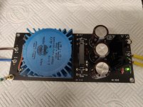
I have two versions of these available. The first is a single rail positive PSU and the second is a dual rail PSU providing positive and negative outputs.
I have done a full write up on the single rail board here.
The single rail PSU is ideal for building into enclosures as stand alone power supplies for headphone amps, DACs and pre-amps.
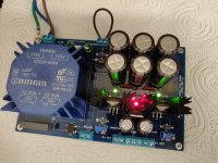
The dual rail PSU is good for building projects that require both a positive and negative supply which you can house all together in the same enclosure. For example I have had a lot of interest in this board for use with Wayne Colburns BA2018 Linestage amp which is quite fitting as after all these PSUs are based in part on the Whammy PSU. I will do a full write up on my site once I get more boards from the fab house hopefully with the correct silkscreen and no lines.")
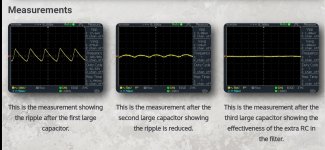
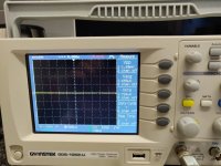
I did my own measurements too with the scope to verify the boards I made are just as effective as Wayne's original design and the readings speak for themselves.
And for anyone that says "why are you using those old noisy regulators?" I added a smoothing cap on the output of the regulator and measured the output with the scope and I can confirm the ripple is just as straight as it is on the 3rd cap in the main filter.
Excuse the lines on the dual rail PCB the fab house messed up somehow with the silkscreen when trying to draw the caps on.
I have plenty of boards so if you are interested then drop me a PM.
I have done a full write up on the single rail board here.
The single rail PSU is ideal for building into enclosures as stand alone power supplies for headphone amps, DACs and pre-amps.
The dual rail PSU is good for building projects that require both a positive and negative supply which you can house all together in the same enclosure. For example I have had a lot of interest in this board for use with Wayne Colburns BA2018 Linestage amp which is quite fitting as after all these PSUs are based in part on the Whammy PSU. I will do a full write up on my site once I get more boards from the fab house hopefully with the correct silkscreen and no lines.
I did my own measurements too with the scope to verify the boards I made are just as effective as Wayne's original design and the readings speak for themselves.
And for anyone that says "why are you using those old noisy regulators?" I added a smoothing cap on the output of the regulator and measured the output with the scope and I can confirm the ripple is just as straight as it is on the 3rd cap in the main filter.
Excuse the lines on the dual rail PCB the fab house messed up somehow with the silkscreen when trying to draw the caps on.
I have plenty of boards so if you are interested then drop me a PM.
Attachments

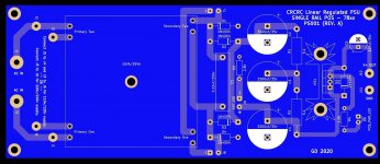
I am not so sure. It looks fine, but the layout could be better. The wires from resistor to resistor of CRCRC-filter have to go from resistor to capacitor pin and only then to the next resistor pin. Such a layout ensures maximum done by caps.
And I would put a RC-snubber after the primary but not just a cap (C1).
And there could be a place for a fuse or fusible resistor or NTC-resistor at the primary.
And I would put a RC-snubber after the primary but not just a cap (C1).
And there could be a place for a fuse or fusible resistor or NTC-resistor at the primary.
Last edited:
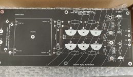
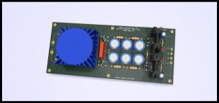
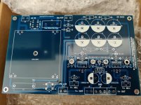
Here is a better one I made in a smaller layout. I disagree with the path for the resistors in the CRC filter. Electricity travels so quick there is no noticeable difference between the way you mentioned and the way I have implemented it. There would even be no noticeable difference if you did point to point. If you look at the scope image you will see layout is still effective.
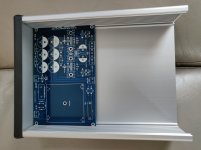
My new boards measures only 160mm x 100mm and slides straight into the rails of a Hammond 1455T2201 enclosure. On board fuse too for those that are fussy and don't want to use an IIEC inlet with onboard fuses.
My new boards measures only 160mm x 100mm and slides straight into the rails of a Hammond 1455T2201 enclosure. On board fuse too for those that are fussy and don't want to use an IIEC inlet with onboard fuses.
Attachments
Close, but still not correct. The current certainly does not stay the same. If it did you would have created free power. Check out this site for the correct formulae.I apologise for the misunderstanding, I meant voltage as the current stays the same. I will amend this now.
Kind regards
https://www.sowter.co.uk/rectifier-transformer-calculation.php
Look at the capacitor input filter bridge example. The mean transformer secondary current is 1.61 times the dc current output.
Cheers
Ian
My designs have been tested and I can confirm that the 1.414 is correct for them including my newest design which uses a rectifier bridge which according to that site should be 1.61. I measured the DC output and it's certainly closer to the 1.414.
This is another reason I put a disclaimer because you should do your due diligence anyway.
This is another reason I put a disclaimer because you should do your due diligence anyway.
You need to read the web site I posted more carefully. It states the transformer ac secondary voltage is 0.7 times the dc voltage across the capacitor which is exactly the same as saying the dc voltage across the output capacitor is 1.414 times the transformer secondary ac voltage..
In addition, this also means that the mean transformer secondary ac current is 1.61 times the dc output current. From the design point of view, what this means it that if you want a dc output current of 1 amp then the transformer secondary needs to be rated a 1.6 amps. However, the transformers you have selected are only rated at 1.136 amps (when paralleled).
Bottom line is if you try to sink more than 700mA from any of the regulators you risk saturating the transformer and it will overheat.
Cheers
Ian
You need to read the web site I posted more carefully. It states the transformer ac secondary voltage is 0.7 times the dc voltage across the capacitor which is exactly the same as saying the dc voltage across the output capacitor is 1.414 times the transformer secondary ac voltage..
In addition, this also means that the mean transformer secondary ac current is 1.61 times the dc output current. From the design point of view, what this means it that if you want a dc output current of 1 amp then the transformer secondary needs to be rated a 1.6 amps. However, the transformers you have selected are only rated at 1.136 amps (when paralleled).
Bottom line is if you try to sink more than 700mA from any of the regulators you risk saturating the transformer and it will overheat.
Cheers
Ian
These power supplies are for preamps and headphone amps which only use low current so none of this will be an issue anyway. I've done my bit by telling folk not to exceed the 1A limit. By which means is entirely their choice.
Hello I think we have some very good points made on this thread and some valid points made by ruffrecords which are very helpful .. but I have ordered a few of these PCBS and they work very very fine indeed even when loaded up with a heavy load. at the end of the day it's a DIY site for learning .. but I can validate the PCB's work very well in my projects so keep up the good work in your PCB design skills adventure
all the best
all the best
Hello I think we have some very good points made on this thread and some valid points made by ruffrecords which are very helpful .. but I have ordered a few of these PCBS and they work very very fine indeed even when loaded up with a heavy load. at the end of the day it's a DIY site for learning .. but I can validate the PCB's work very well in my projects so keep up the good work in your PCB design skills adventure
all the best
Thank you for your kind comments James, I don't just throw these boards together I do alot of testing myself loaded and unloaded and ensure there are ample safety protocols in place for safety and peace of mind. I am not the best at explaining things sometimes but I do try and get my point across.
Did you get chance to build the new Bi-Polar PSU with the LM29xx regulators?
It was not my aim to criticise the design. The OP himself said you need to do your own due diligence and that is just what I am doing. I happen to be in the process of designing a similar PSU (for a tube HT supply) so I am obviously keen to look at other designs with similar attributes.
In particular I am quite interested in the idea of housing the power transformer on the PCB. it saves an awful lot of wiring. My intitial design uses a PCB mounting SMPS for the heater supply and a linear CRCRC topology for the HT. The transformer I have selected for the HT is this one:
IF-18-230 Bel Signal Transformer | Mouser United Kingdom
it has international primaries and a pair of 115V secondaries that wired in series provide 230VAC. I purchase a sample from Mouser. It is an 18VA type similar in size to the 25VA type the OP has used in his design. Having obtained the sample and hefted it in my handI am now concerned about the mass of the transformer and the strains it might place on the PCB in the presence of vibration.
From the pictures on the OP's web site I can see fixing holes at either end of the PCB but it is not clear if it was necessary to add further support near the centre of the PCB to stop the transformer from flexing. I know in normal use it it will not be bounced around but if I build this into a device and send it to someone I am concerned that it might be damaged during shipping.
Cheers
Ian
It was not my aim to criticise the design. The OP himself said you need to do your own due diligence and that is just what I am doing. I happen to be in the process of designing a similar PSU (for a tube HT supply) so I am obviously keen to look at other designs with similar attributes.
In particular I am quite interested in the idea of housing the power transformer on the PCB. it saves an awful lot of wiring. My intitial design uses a PCB mounting SMPS for the heater supply and a linear CRCRC topology for the HT. The transformer I have selected for the HT is this one:
IF-18-230 Bel Signal Transformer | Mouser United Kingdom
it has international primaries and a pair of 115V secondaries that wired in series provide 230VAC. I purchase a sample from Mouser. It is an 18VA type similar in size to the 25VA type the OP has used in his design. Having obtained the sample and hefted it in my handI am now concerned about the mass of the transformer and the strains it might place on the PCB in the presence of vibration.
From the pictures on the OP's web site I can see fixing holes at either end of the PCB but it is not clear if it was necessary to add further support near the centre of the PCB to stop the transformer from flexing. I know in normal use it it will not be bounced around but if I build this into a device and send it to someone I am concerned that it might be damaged during shipping.
Cheers
Ian
It's fine I appreciate everyone's feedback. That transformer is hefty over 6KG!! Luckily the toroidal ones I use weigh far less and because the length of the PCB is only 160mm flexing is not an issue it's really fairly rigid. I did test this too. I try to cover every scenario. My previous Bi-Polar design did have centre fixings because it's length was 220mm and it did have a good amount of flex in the middle.
The Mouser page is deceptive. I just weighed the transformer I have and it is only 391 grams. No idea where Mouser got 6.8Kgm from. The L01-6365 you used weighs over 500 grams according to its data sheet so we are definitely in the same ball park. I am still very tempted to add two more fixing holes at the centre even if I do not end up using them.
I once shipped a 3U high 19 inch rack mounting unit to Germany. For one of the supplies I used a 100VA toroid that had and epoxy filled centre with a hole though it, fixed in the usual way to the side of the unit it an M5 bolt. When it arrived, the epoxy had shattered and the transformer had flapped about doing considerable damage. So you can see I am a bit sensitive to transformer fixings.
Cheers
Ian
- Home
- Amplifiers
- Power Supplies
- Simple Linear CRCRC PSU