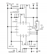
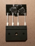
Recently I finished this Ideal-Bridge project that I call Kool-BRG. It was designed around LT4320 active driver for MOSFET bridge on a PCB layout serving as a drop-in replacement to the popular 4-pin single-in-line rectifier bridges. I made two versions of PCB design, Kool-BRG-L for the 10-7.5-7.5 mm pin pitch bridges, and a more compact Kool-BRG-S for the 5-5-5 mm pin-pitch bridges.
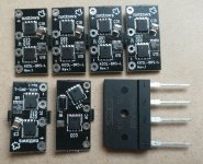
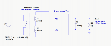
I built 8 Kool-BRG-L units for some upcoming projects and put them to a load test comparing with a Sanken "normal" bridge. The low forward drop and cool operation were just as anticipated. No surprises there. At a DC load current of 1.56A, the Sanken diode bridge is hot to the touch, presenting a temperature rise of about 40C. With the Kool-BRG the load current is slightly higher through the same 32-ohm dummy load resistor, at 1.6A, due to the much lower forward drop on the rectifier devices, hardly any temperature rise could be felt or measured at all.
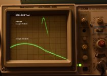
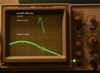
What impressed me the most was how much more smoothly and quietly the Kool-BRG switches than its counterpart does. The scope shots show the spike and ringing that take place at the moment of cutoff. The conventional diode bridge is seen presenting a substantially greater amplitude.
Just in case it could be confusing, I want to make it clear that the noise waveform, i.e. the spike and the ringing, on the scope shots are NOT what presents at the DC output across the Vout and GND, nor does the absolute amplitude of the noise have any bearing towards how much of an EMI problem there might be. The scope was probing across the 10,000uF capacitor, and I would get the same noise waveform when I probe on the ground clip of the scope that is attached to the capacitor's negative lead. The waveform is coupled into the scope as common mode noise.
That being said, however, the contrast in waveform does seem to suggest one is much quieter than the other.
I built 8 Kool-BRG-L units for some upcoming projects and put them to a load test comparing with a Sanken "normal" bridge. The low forward drop and cool operation were just as anticipated. No surprises there. At a DC load current of 1.56A, the Sanken diode bridge is hot to the touch, presenting a temperature rise of about 40C. With the Kool-BRG the load current is slightly higher through the same 32-ohm dummy load resistor, at 1.6A, due to the much lower forward drop on the rectifier devices, hardly any temperature rise could be felt or measured at all.
What impressed me the most was how much more smoothly and quietly the Kool-BRG switches than its counterpart does. The scope shots show the spike and ringing that take place at the moment of cutoff. The conventional diode bridge is seen presenting a substantially greater amplitude.
Just in case it could be confusing, I want to make it clear that the noise waveform, i.e. the spike and the ringing, on the scope shots are NOT what presents at the DC output across the Vout and GND, nor does the absolute amplitude of the noise have any bearing towards how much of an EMI problem there might be. The scope was probing across the 10,000uF capacitor, and I would get the same noise waveform when I probe on the ground clip of the scope that is attached to the capacitor's negative lead. The waveform is coupled into the scope as common mode noise.
That being said, however, the contrast in waveform does seem to suggest one is much quieter than the other.
Attachments
Cool and quiet is good but very expensive compared to "traditional" methods.
That's true. I had hoped the price would go down after a while but it never did.
However if one happens to want to squeeze every mV out of a transformer in hand plus a super quiet rectifier this could still be an option over buying another transformer, perhaps.
@nattawa
Did. your set Up include a snubber across the Transformer‘s secondary?
Thanks,
Winfried
No, I did not set up to do that test. The test I did was to compare the two rectifiers "naked".
I have Quasimodo snubbed positive and negative full wave hexfet bridges in my preamp, dac, phono, and power amps, but they were built before LT3040 was available. The Quasimodo snubbing is quite effective and costs a dollar to try. Today i’d try the snubbing and the LT4420 on my next power amp build.
I’m actually in Mississauga too, North west end of it
I’m actually in Mississauga too, North west end of it
Hi
Any plans to offer this on sale or provide the Gerber and a BOM with the DIY community?
Cheers!
Hi bravi,
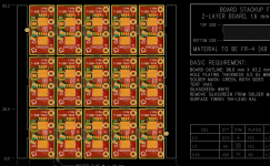
I did have that plan remotely in mind when I started the project, although I doubted (still do) there would be much interest out there unless the price of LT4320 has gone down in a substantial way, however the likelihood. In fact the PCB design for the prototype was done to form a production panel of 15 units (24 for the more compact KOOL-BRG-S) that's ready to go on a SMT assembly line. But that latter part doesn't seems to be going to happen any time soon
")
PM me if interested in small qty PCBs (un-assembled boards only).
Attachments
The power supply together with the chassis are the most expensive parts of any DIY amplifier.
While the IC is surprisingly expensive, it also allows to save a bit on the transformer and you don’t need heat sinks for the rectifiers.
Technical advantage often has a price.
What is the point of saving a few Euros?
I see the biggest advantage of this solution in high current applications though.
For reducing emissions, snubbers across the rectifiers work well.
More elegant is to avoid emissions in the first place.
- Home
- Amplifiers
- Power Supplies
- Impression of LT4320 and Ideal-Bridges. They are cool, and quiet too.