I'm thinking about making a non-isolated plate amplifier for subwoofer usage (top end pro 18/21" cabs). The audio inputs will be isolated but the speaker output will not be, a RCBO will be utilized on the line input for ensure safety and no non isolated terminals will be externally accessible. The aim of this is to reduce the parts count, size and increase efficiency.
In terms of the power supply my current plan is to use an interleaved PFC stage with a continuous power throughput capability of 3.5 kW to make a soft regulated 400VDC bus which will power the amplifier (bridged low switching frequency IGBT class D). I haven't designed a PFC before so I have a few questions:
1) What restrictions are there on the maximum output capacitor size on a boost PFC? (this is where I want to store energy for transients)
2) How easy is it to current limit the line voltage? (IE I would like to not exceed 13A average line current) (considering normal boost converters may be impossible....)
3) In the circumstance that the line current is limited the output capacitor bank will begin to sag, this would seem to be problematic if it goes below the peak line voltage?
So considering this am I just better boosting to a higher voltage and using a buck converter to perform the current limiting and limiting of the maximum sag on the PFC output capacitor?
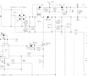
I'm confused the attached picture appears to show a flyback and no PFC?
Regarding compliance issues with safety there should be no problem, I have explained above how safety will be ensured using two independent methods one of them consisting of an externally certified safety device and only certified isolatorswill be used for external connections.
Regarding compliance issues with safety there should be no problem, I have explained above how safety will be ensured using two independent methods one of them consisting of an externally certified safety device and only certified isolatorswill be used for external connections.
I'm not getting the kind of responses I was looking for here, it there a better forum for discussion of power supplies? I have designed plenty of power supplies in the past for exotic applications just lack familiarity with PFC. (mainly my expertise is in high frequency resonant switchers like class-E inverters)
In terms of what I have decided to do I have decided to have the following structure:
PFC -> buck converter -> full bridge class D
mainly as its easy to get the buck converter to current limit and smoothly transition between controlling the output voltage and limiting the output current.
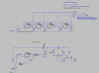
The buck converter will be operating in current mode with peak current limiting which will limit the overall continuous power flow through the system. It will also have 4 phases and switch at 200kHz (800 kHz effective switching rate). I found some of the literature inaccurate on actual practical implementation of this type of modulator, specifically you want to use a D-type flipflop not an SR latch in the modulator. I haven't been able to find an off the shelf controller that is usable with 390V DC input so will implement my own controller.
For the PFC I found this design:
http://www.ti.com/lit/ug/tidube1c/tidube1c.pdf
which looks to be almost what I want, what do people think?
In terms of what I have decided to do I have decided to have the following structure:
PFC -> buck converter -> full bridge class D
mainly as its easy to get the buck converter to current limit and smoothly transition between controlling the output voltage and limiting the output current.
The buck converter will be operating in current mode with peak current limiting which will limit the overall continuous power flow through the system. It will also have 4 phases and switch at 200kHz (800 kHz effective switching rate). I found some of the literature inaccurate on actual practical implementation of this type of modulator, specifically you want to use a D-type flipflop not an SR latch in the modulator. I haven't been able to find an off the shelf controller that is usable with 390V DC input so will implement my own controller.
For the PFC I found this design:
http://www.ti.com/lit/ug/tidube1c/tidube1c.pdf
which looks to be almost what I want, what do people think?
Most, many, PFC circuits shape the line current to follow the line voltage. In other words they control the line current. They generally do this using average current mode control and a current error amplifier. The input to the current error amplifier is from the voltage error amplifier via a 1/v^2 conditioner. You can simply and precisely control average current demand by limiting the output of the voltage error amplifier. You can simply and precisely control peak current demand by limiting the input to the current error amplifier.
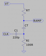
If you wish to implement a multiphase pfc then you might consider using the functionality of a main pfc controller ic, multiplier/divider voltage error amplifier to provide a main current demand signal and feed that to independent PWM controllers, UCC35705?, bent to perform average current mode control of the power switches... add an LM324. Synchronise from a ring counter by injecting clocks into the bottom of the ramp generators.
...
...
Attachments
The PFC will be single phase AC and single phase switching. I think I need the buck stage (which is 4 phase) because if you consider what happens when you short the DC bus of a typical boost PFC an unlimited current will flow through the rectifier.
Fiddling with the buck converter is going well, just implemented duty cycle restriction logic to ensure my high side drive maintains its bootstrap voltage.
I'm sensing the inductor current for the buck on the low side as the output isn't ground referenced and this avoids needing to voltage shift and common mode problems.
You could go mad and consider a SEPIC.
http://www.ti.com/lit/ml/slup103/slup103.pdf
http://www.ti.com/lit/ml/slup104/slup104.pdf
Or just implement an absolute shut down with a Mosfet in the ground leg.
http://www.ti.com/lit/ml/slup103/slup103.pdf
http://www.ti.com/lit/ml/slup104/slup104.pdf
Or just implement an absolute shut down with a Mosfet in the ground leg.
I'm not forcing you to use a SEPIC but your dismissal makes sense because the paper mentions the issue and provides recommendations as to how to avoid the issue and... it's much easier to implement a 400V four phase buck convertor becoz level shifting drivers, as long as you sort out the minimum dead time and becoz buck convertors do not use control loop theory.
¯\_(ツ)_/¯
¯\_(ツ)_/¯
Thanks for the simulation I will check it out. I missed that they had addressed the issue, I have a habit of rapid scanning papers and finding any reason not to read them further in more detail due to having to read thousands of papers in the past.
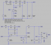
In return I attach my current efforts with the buck. This is just some messing around with a simple single phase buck to get the practical implementation details right in my head. Its a peak current mode single phase buck with duty cycle limiting and fixed slope compensation for D=0.7. Vi = 10V, Iout = 1A. Haven't put the voltage loop on it yet; had a lot of issues with the slope compensation. If this where made multiphase I would have to use something like GMR current sensors on the inductors rather than sensing on the low side. It was important to me that the whole design is clocked rather than relying on monostables, short pulses etc.
In return I attach my current efforts with the buck. This is just some messing around with a simple single phase buck to get the practical implementation details right in my head. Its a peak current mode single phase buck with duty cycle limiting and fixed slope compensation for D=0.7. Vi = 10V, Iout = 1A. Haven't put the voltage loop on it yet; had a lot of issues with the slope compensation. If this where made multiphase I would have to use something like GMR current sensors on the inductors rather than sensing on the low side. It was important to me that the whole design is clocked rather than relying on monostables, short pulses etc.
Attachments
Take a leaf out of Loud Technologies PFC build;
Look up SRM450 Mk2 for more details.
There will be compliance issues with safety so DO NOT use raw mains and no isolation!
This is not a PFC. This is a boost converter after a conventional rectifier and before an unregulated transformer stage, which minimizes output fluctuations regardless of line voltage drop.
kipman725:
Given tha fact that about +/-200V or +/-250V is usually enough to get the biggest conventional voice coil subs out of Xmax (haven't you checked that?), and that there are MOSFET for that BTL voltage with reasonable Qrr:
You could go with the project that the company for which I worked rejected.
A buck-boost PFC. Switches at both sides of inductor hehe
MorbidFractal:
That TTI QPX1200 SERVICE MANUAL is really obfuscated but inspiring.
Last edited:
... Yes. They use Cadstar which forces you to draw rubbish circuit diagrams. The PFC is not interleaved but otherwise there are a few tricks in that one. Their lower powered models use magamps for post regulation followed by a linear pass device. The IV curves result from considerations of the duty cycle of utilisation of the main transformer.
Hey Eva, so the idea of the 300V bus with BTL amp is not that full output is used but for energy storage. The amp is intended to always operate with a peak limiter below its actual peak output and not to sustain it peak absolute power output. The limiter will be such that if the bus starts to sag the gain will commensurately be reduced. The aim is to get the most sub output with real music signals from a UK 13A, 230V socket, while drawing nice sine wave currents for generator usage. The amp will use IGBTs for cost reasons, if switching frequency is limited (after all this is a dedicated sub amp) then they can take a lot of current in low cost devices.
Will check out the buck boost PFC
Will check out the buck boost PFC
MorbidFractal: If diodes that are efficient at 1200A/us are not available, there is always the option to use 6 diodes which are efficient at 200A/us. The usage of 6 MOSFET is for reducing EMI, all operated at 1/6th the di/dt. Interestingly this is as expensive as SiC or GaN, but far more rugged. Conduction-loss wise it also outperforms SiC and GaN. It is only not so effective capacitive-loss wise.
kipman725: Start doing conceptual simulations of PFC regulation loops. Output ripple and sag is inversely proportional to output capacitance. Huge capacitance in the range of few dozen mF results in few volts ripple and sag, without extra voltage margin. The bandwidth of the loop has to be adjusted depending on line voltage, at 2 times less line voltage 4 times more gain is allowed. This requires VCA or digital processing. I think there is also a method developed by IR based in integrators and inductor current slopes. The output of the voltage loop is not either voltage or current, it is a power command. VCA wise there is the good old L4981 IC. The buck-boost idea based in switches at both sides of the inductor requires a little hell of sequentiation logic for transition between operating zone A and zone B. The SEPIC idea requires many inductors and capacitors, and to operate the switches at voltages and currents fat higher than line input or regulator output voltages and currents. The interleaved idea for high voltage IMHO is just a game from ST or TI to sell chips, for low voltage it results in higher bandwidth and lower current through each part, as for 12V to 1V 100A computer CPU regulators.
kipman725: Start doing conceptual simulations of PFC regulation loops. Output ripple and sag is inversely proportional to output capacitance. Huge capacitance in the range of few dozen mF results in few volts ripple and sag, without extra voltage margin. The bandwidth of the loop has to be adjusted depending on line voltage, at 2 times less line voltage 4 times more gain is allowed. This requires VCA or digital processing. I think there is also a method developed by IR based in integrators and inductor current slopes. The output of the voltage loop is not either voltage or current, it is a power command. VCA wise there is the good old L4981 IC. The buck-boost idea based in switches at both sides of the inductor requires a little hell of sequentiation logic for transition between operating zone A and zone B. The SEPIC idea requires many inductors and capacitors, and to operate the switches at voltages and currents fat higher than line input or regulator output voltages and currents. The interleaved idea for high voltage IMHO is just a game from ST or TI to sell chips, for low voltage it results in higher bandwidth and lower current through each part, as for 12V to 1V 100A computer CPU regulators.
Last edited:
(Note: SiC and GaN enthusiasts for non RF applications boast the chance of doing 400V and up switching at 500Khz or up, for the sake of a smaller inductors, but how an inductor capable of 400Vp-p 500Khz could be reduced so much in size? Special ferrites not invented yet? New periodic table elements? Iron powder won't do it. Air core won't do it without lots of leakage or lots of inductance for reducing volts per turn. In the end a lot of inductance is still required at high voltage, to control flux swing rate (what could be called dB/dt). But with a lot of inductance switching frequency can be lower. >250Khz requires ferrite. Ferrite requires gap. Gap not covered by winding area is leaky. Gap covered by winding area requires litz wire. Litz wire 0.1mm is ~200% bulkier. These guys have no experience in magnetics design, they just make a specification and ask for bids. Gambling is not engineering, there is not always a solution for gambling. Then the game ends and a new game starts. Hey, but the authoritarian gambler "enforce a solution" often gets ripped in the process.)
Last edited:
Hey EVA I have a lot of experience with this you use low permeability cores, iron powder with a binding agent in the 1 - 10Mhz range (try around u=100). Litz is only good up to around 3 MHz beyond that point you want copper tape or large diameter solid core conductors. Above that (say for example a 27MHz converter) you want to use air core magnetics. I have seen multi kW power flows in converters operating in the 10's of MHz with >90% efficiencies. In terms of topolgies look into class-E modulators and rectifiers.
- Status
- This old topic is closed. If you want to reopen this topic, contact a moderator using the "Report Post" button.
- Home
- Amplifiers
- Power Supplies
- Energy storage in non isolated amplifier PFC stage