http://www.ti.com/product/OPA1611/toolssoftware
http://www.ti.com/product/OPA1622/toolssoftware
http://www.ti.com/lit/zip/sbom396
http://www.ti.com/lit/zip/sbom957
Assume you trust the modelling. If you open the .lib files in a text editor you can see that it appears to be fairly extensive.
LTSpice claims to be or is PSpice compatible. You might look on TI for their design tools using TINA however...
LTspice | Design Center | Analog Devices
From the two above .zip files there will be a .lib file. Place them in the directory where you set up your LTSpice model. Open LTSpice and make a new schematic. Place an opamp2. Give it the name of the model with no extension, LM1611. Place a .LIB LM1611.LIB spice directive. Connect other parts and simulate.
OK... it's in the attached .zip file.
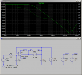
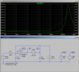
Use VAC and plot V(a)/V(b) to get the loop gain. Use IAC and plot V(b)/I(IAC) to get output impedance. Set the one you are not using to zero. You have to right click on the axis to get linear vs dB and turn phase on and off.
You can add ESR and ESL within the capacitor model or model them as external components. The same for traces if you find one of those web calculators.
Have a play. Shout if it goes wrong.
http://www.ti.com/product/OPA1622/toolssoftware
http://www.ti.com/lit/zip/sbom396
http://www.ti.com/lit/zip/sbom957
Assume you trust the modelling. If you open the .lib files in a text editor you can see that it appears to be fairly extensive.
LTSpice claims to be or is PSpice compatible. You might look on TI for their design tools using TINA however...
LTspice | Design Center | Analog Devices
From the two above .zip files there will be a .lib file. Place them in the directory where you set up your LTSpice model. Open LTSpice and make a new schematic. Place an opamp2. Give it the name of the model with no extension, LM1611. Place a .LIB LM1611.LIB spice directive. Connect other parts and simulate.
OK... it's in the attached .zip file.
Use VAC and plot V(a)/V(b) to get the loop gain. Use IAC and plot V(b)/I(IAC) to get output impedance. Set the one you are not using to zero. You have to right click on the axis to get linear vs dB and turn phase on and off.
You can add ESR and ESL within the capacitor model or model them as external components. The same for traces if you find one of those web calculators.
Have a play. Shout if it goes wrong.
Attachments
Thanks very much for simulating that! Things just got a tad clearer for me...
I'll take a step back though and explain why we arrived at the values for the caps that were chosen as of now. So what is it that we are seeking for? Well, the ideal voltage source which has zero output impedance over the needed frequency range. As zero is not possible, let's look at a more realistic approach.
The ESS has 0dB PSRR on the AVCC pin, it's a reference voltage. So to achieve a SNR of 125dB for example the noise voltage on the AVCC pin must not exceed 3.3V/125dB which equals 1.8uV. if we say the current swing demanded by the AVCC pin is 8mA the output impedance of the regulator must no exceed 0.2mOhms or otherwise the current will modulate the voltage by more than these 1.8uV (Hope there is no error in my calculation). Even if I would use an Opamp with no capacitance at all it will not be able to have such a low Zout over the whole frequency range that we need it to operate at. Keep in mind that this is a SD DAC which modulates in the MHz region. So we quickly came to the conclusion that there's no way we would get away without a cap across the AVCC supply. So we did quite a long search to find a suitable capacitor combination that a) does not induce resonances from the package inductances and will b) have a low impedance over a wide frequency range. That's why we ended up with a 1812 10uF MLCC in parallel with a four terminal feedthrough cap from TDK, 0603 package, 4.7uF.
/
I think your reasoning is OK. But there's another issue: have you calculated the impedance of say 1inch wiring/trace between the opamp output and the AVCC terminal?
We ran into that with the design of the superregulator, and we decided to include remote sensing. That way, you can place the regulator at some distance and still regulate at the point of load. See the article here.
Jan
Last edited:
I think your reasoning is OK. But there's another issue: have you calculated the impedance of say 1inch wiring/trace between the opamp output and the AVCC terminal?
We ran into that with the design of the superregulaor, and we decided to include remote sensing. That way, you can place the regulator at some distance and still regulate at the point of load. See the article here.
Jan
I was planning to place the 4.7u four terminal cap right next to the AVCC pin, maybe only 1-2mm away, and also the 10u right next to it. I could do remote ground sensing with a diff amp and also get the nfb for the positive input terminal right at the avcc pins. do you think that will make a difference given that the pole created by the caps is probably down in the 10s of kHz (!). Will be able to say more after I simulated this...
One more thing, this would mean that I'd have to work with two Opamps anyway, because there are two AVCC pins...
I was planning to place the 4.7u four terminal cap right next to the AVCC pin, maybe only 1-2mm away, and also the 10u right next to it.
Yes but that mneans you don't have the very low regulator Zout at AVCC available, so the performance of the opamp regulator becomes a bit moot.
One more thing, this would mean that I'd have to work with two Opamps anyway, because there are two AVCC pins...
Absolutely. That goes without saying. If not, the whole discussion is a bit useless.
The best results will be with two independent regulators with remote sensing. There's not much point in having a low Zout at the opamp output, you need it at AVCC.
Jan
I have a question about remote sensing: If I only want to do remote sensing for the output of the opamp that seems very intuitive, i just take the feedback from the avcc pin directly.
BUT: If I wanted to also do remote ground sensing, where would the correct point for that to grab the feedback from? one point is the negative terminal of the RC lowpass cap as that's the reference's negative terminal. But the second one? If the I/V opamp + input terminal was connected to ground, would that be the correct point to get the feedback from? First It seemed so logical to me, now I can't wrap my head around it...
BUT: If I wanted to also do remote ground sensing, where would the correct point for that to grab the feedback from? one point is the negative terminal of the RC lowpass cap as that's the reference's negative terminal. But the second one? If the I/V opamp + input terminal was connected to ground, would that be the correct point to get the feedback from? First It seemed so logical to me, now I can't wrap my head around it...
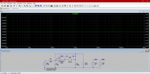
@MorbidFractal: I just installed LTSPICE, opened the simulation files you provided and got a weird result (attached). So I guess I have to adjust some simulation options... I clicked through them but can't seem to find anything obvious. Probably bloody beginners fault ")
Attachments
Would you care to cite a reference please? Or did you simulate that? Or even measure it?
Use an OPA1622 wired for unity gain with a 3.3V non inverting input, place ferrite bead (90n||100R), 100u aluminum electrolytic and 10u ceramic on the output and look at the impedance. It's two orders of magnitude higher impedance.
@MorbidFractal: I just installed LTSPICE, opened the simulation files you provided and got a weird result (attached). So I guess I have to adjust some simulation options... I clicked through them but can't seem to find anything obvious. Probably bloody beginners fault
Depending on the analysis you are doing you have to set VAC or IAC to 1 with the other being 0. In the one your picture shows. Set IAC to 0 and VAC to 1. Right click. Click on Advanced. AC is on the upper middle right.
Oh... or you can just right click on the AC 1V and edit it directly.
Last edited:
@MorbidFractal: I just installed LTSPICE, opened the simulation files you provided and got a weird result (attached). So I guess I have to adjust some simulation options... I clicked through them but can't seem to find anything obvious. Probably bloody beginners fault
You are measuring the voltage across a voltage source. Of course that is constant ...
Jan
You are measuring the voltage across a voltage source. Of course that is constant ...
Jan
It's non-intuitive.
Does my head in as well but you are measuring the ratio of either side of the voltage source with respect to ground.
- Status
- This old topic is closed. If you want to reopen this topic, contact a moderator using the "Report Post" button.
- Home
- Amplifiers
- Power Supplies
- Using OpAmps as Voltage Regulators