Totally struggling with how to get a start on this!
I'm in the UK (240v) and transformers (toroidal) are 300VA 50-0-50's (in a pair of monoblocks that I'm restoring)
Presently...the only protection is a 3A fuse at the wall plug!
Want to protect both primary/2ndary...and tbh...haven't a clue how to go about deciding on appropriate value of fuses
I have A-level Physics, (dim and distant past I'm afraid) and can recall my P=IV, and V/I=R...etc...but don't know where to start here.
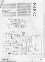
Have attached PSU circuit diagrams, and hope that someone out there might 'walk me through' the process of calculating fuse values!!??
Perhaps there's some kind of fuse 'calculator' out there that could help??
Many Thanks
I'm in the UK (240v) and transformers (toroidal) are 300VA 50-0-50's (in a pair of monoblocks that I'm restoring)
Presently...the only protection is a 3A fuse at the wall plug!
Want to protect both primary/2ndary...and tbh...haven't a clue how to go about deciding on appropriate value of fuses
I have A-level Physics, (dim and distant past I'm afraid) and can recall my P=IV, and V/I=R...etc...but don't know where to start here.
Have attached PSU circuit diagrams, and hope that someone out there might 'walk me through' the process of calculating fuse values!!??
Perhaps there's some kind of fuse 'calculator' out there that could help??
Many Thanks
Attachments
Last edited:
Fuses usually have to be twice as normal work current rated (in average).
So for 300 VA transformer, for primary, we need: 300VA/240V = 1.25 A primary rated current, so fuse can be 2.5 -3.0 A rated. (don't forget about NTC-termistor for inrush current limiting if it is toroidal transformer, 2-7 R can be ok).
For secondary we have: 300VA/(2*50V) = 3 A secondary rated current, so use a fuse with 5-8 A rated current.
Fusing only primary is usual way.
Last edited:
For a transformer primary you need a slow-blow type fuse, otherwise it'll probably just fail on the inrush current pulse. Slow blow have more thermal inertia to cope with short overloads. Fuses are normally to prevent faults becoming fires.
Fuses _after_ the filter caps in an amp can be fast-blow and help prevent cascade damage if the amp develops a fault - a shorted secondary itself ought to cause the primary fuse to blow, especially if its a major winding. Small auxiliary secondaries might be able to sustain a short without blowing the primary fuse, they are a candidate for individual fuses.
Fuses _after_ the filter caps in an amp can be fast-blow and help prevent cascade damage if the amp develops a fault - a shorted secondary itself ought to cause the primary fuse to blow, especially if its a major winding. Small auxiliary secondaries might be able to sustain a short without blowing the primary fuse, they are a candidate for individual fuses.
Normally there is also a thermal fuse inside the windings. If it gets hot say above 60 or 80 degrees, it opens. You could fit something similar in contact with the trafo or inside the case. Measure the transformer temp while operating and at idle and then give a bit margin for room temp changes.
Some more info in link - mainly focused on valve amp applications, but many similarities.
Do you have an rms current meter or similar method using sense resistor, for secondary side measurement? A cheap plug-in power/energy meter is very convenient for AC current measurement.
https://dalmura.com.au/static/Valve%20amp%20fusing.pdf
Do you have an rms current meter or similar method using sense resistor, for secondary side measurement? A cheap plug-in power/energy meter is very convenient for AC current measurement.
https://dalmura.com.au/static/Valve%20amp%20fusing.pdf
Usually we use fuse only in a primary circuit. Because it must be there.Can I 'get away' with just protecting the Primary.....?
As for secondary - you may need some additional reasons to put fuses there. For example if you are not sure in parts quality or you want to do some experiments with secondary circuits.
You can't "protect a transformer" with a fuse.
Happy operation may be 100VA in, 90VA out, 10VA of heat in the windings. The PT thermal design is based on the 10VA loss.
A partial short "could" be 100VA in, 0 VA out, 100V of heat in the windings. The PT runs 10Z as hot as designed, and smokes. But the fuse only saw the "happy" 100VA input.
Fuse so your line cord can't burn and set the carpet on fire. (As I understand UK custom, this is built-in.)
PRR, that description relates to primary side fusing, and a fault that draws full rated line current (which a primary side fuse has to pass to allow correct operation of the equipment). Any equipment fault where primary side current is constrained to not much more than rated primary current could for sure damage the power transformer, unless the fault is on the secondary side of the transformer and is cleared by some action on that side (eg. faulty part going open-circuit, or secondary fusing).
Can a fault on secondary side cause a primary side current to exceed the rated primary current - sure there are situations, but the buffering of the fault by the transformer impedances may not cause such a primary over-current multiplier as to blow a primary fuse before transformer damage occurs - so not a clear cut outcome.
Given the reliability of a power transformer (from faults occurring within the transformer and not due to secondary side actions), then any practical focus on fuse protection moves to the secondary side, and as you indicate the primary side fuse can't be relied upon.
Is that JLH amp? I always put fuses on the secondary side on the AC going into the bridge on amps I build. Some say it's not needed but the amount of times I've had fuses blow whilst getting a project up and running... Most commercial 70's amps have two such fuses on the PCB.
The way I understand it is the primary fuse is there to protect in case of a catastrophic short, secondary fuses to protect in case of partial shorts.
I tend to use a thermistor and or soft start circuit and slightly underated slo blo fuse on the primary, measure the sec current draw & put suitable fast fuses on each rail.
I was also advised to put a fuse on the ground, but can't remember the where's and whyfors.
Use an analogue meter to measure inrush current on the primary.
Andy.
Last edited:
Yes Andy...it's the JLH 80W monoblock!
Reading through the JLH manual....the only reference to fuses is to the 5A (at least!) one that should be in the wall plug! (suggests to me...at any rate...that a 3A fuse at the wall, would be tripped by the inrush.
Oddly...there are no fuses present inside the case.
If I was to go for a 3.0A slo-blo on the primary...would that be a good starting point? (Just narrowing the discussion to my task!)
Also....will be replacing all 4 reservoir caps(2 x Monoblocks)
These are 4700uf/63v presently.
Is there any advantage in up-rating replacements to...say...10000uf/80v...or should I just stick to original spec.?
"Yes Andy...it's the JLH 80W monoblock!" Is this built with the original PCB's then available for sale? I have most of the ETI's for this period and have been looking at building this amp myself, however T03 mosfets are getting hard to find and expensive, PNP T03's rare as rocking horse s**t. For those prices I could buy a tooob. Whinge over.
3A slo should be fine, better under rated than over rated. Re, replacing the reservoir caps, what's your mains tfmr like? Is it a decent brand like ILP/Antrim and at what VA is it rated? If you increase/double the capacitance, your tfmr has to supply that current through your BR, if it's not up to the job it will get hot and possibly the insulation will breakdown.
I recently recapped a HH S500D, the rails were over 63v, so I bought 80v rated caps, therefore measure the voltage on your rails. To find out if your tfmr is up to it, load it with some big resistors, lightbulbs or whatever & do the maths. At a rough guess you need about 3/4A @ 25v to get 80w, so 63/3 = 21, so two 20r 50w resistors should do the job. If your tfmr runs cool with no noise, reduce the loads till V falls by 10%, that's your tfmr current limit.
Andy.
Last edited:
Thanks Diabolical Artificer.
Plan to get these up to sppeed for myself...so not selling on I'm afraid.
Transformers are bespoke from Tiger-Toroids...
Had to compromise a little on power rating, in order to get right physical dimensions.
I understand these to be rated as 280VA 50-0-50...as opposed to the original 300VA 50-0-50.
Searching around on t'web....found that there was an alternative transformer spec....being 225VA 50-0-50...so figured the 280VA to be in the right 'ball park'
Although confident in terms of the arithmetic...I lack the capacity for the 'hands on' interventions that you refer to in your para. 3
A 250 to 300VA toroid is going to need something of the order of a T3.15A or T4A for the primary, otherwise you may get nuisance blowing at switch on if the conditions happen to be right.
(Inrush current has more to do with both how magnetised the core is, and that is an unknown as it depends totally on what point in the AC cycle the power was removed when it was last turned off and also the point on the cycle when power is turned on again)
The mains plug fuse needs to be a 5A for the same reasons.
300VA doesn't really need a slow start imo although these things have become fashionable in recent years. Above 300VA and its probably worth looking into.
Secondary fusing depends on the load expected and the inrush current to the reservoir caps. Again a lot of unknowns because even a little wiring resistance from transformer to bridge and from bridge to caps can dramatically reduce peak currents.
Quite a few big commercial amps don't even fuse the secondaries and here they assume that a major overload will saturate the transformer and cause the primary fuse to blow.
Thanks Mooly....will be stocking up on 3 to 4A fuses at my local RS counter this week!
Have now decided just to fuse the Primary....keep things simple!!
Any more thoughts out there on replacing/upgrading the reservoir caps?
The Hart Kit parts list gives them as 4700uf/63V....but that was 20+ years ago, and caps have become physically smaller (and cheaper?)
Wondered if going to a higher level of capacitance would be worth it...I'm having to replace all 4 caps anyway...so now is the time!!
I'm not a huge fan of oversized caps tbh. They give the transformer a hard time when the rails are heavily loaded.
The transformer has to top the caps up every half cycle, a bigger cap means the same energy still has to be put back in, but now over a shorter space of time. Why shorter? Because the oversized cap has caused the voltage to sag less between peaks and so the bridge rectifier will not conduct until that voltage point is crossed. That means the transformer/diode current peaks are that much higher per half cycle. A regulated supply means you can relax the cap value somewhat, as long as the ripple rating is sufficient.
I wouldn't go higher than say 6800uF in total per rail for that PSU.
- Status
- This old topic is closed. If you want to reopen this topic, contact a moderator using the "Report Post" button.
- Home
- Amplifiers
- Power Supplies
- How to calculate fuse values to protect Primary/Secondary windings....please!!