
This should explain it for you.
Series Connected Secondary Transformer - Electrical Engineering Stack Exchange
Series Connected Secondary Transformer - Electrical Engineering Stack Exchange
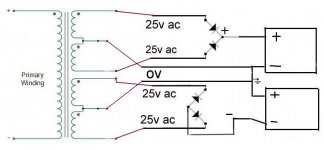
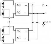
First connect both secondaries in parallel, i.e. connect dot to dot, CT to CT and non-dot to non-dot. Then connect the rectifier's 1st ~ terminal to the dotted secondary terminal and the 2nd one to the non-dotted one. Connect both electrolytics in series, as you've done it yet. Connect the jumper between both 'lytics to the CT's, connect the rectifire's + terminal to the upper 'lytic's + terminal and the rectifier's - terminal to the lower 'lytic's - terminal. Thus the + terminals will show +35 Vdc at idle and the - terminals will show -35 Vdc wrt CT/jumper.
Best regards!
Best regards!
")
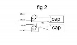
Your Fig 2 will give exactly the +/-35 V you want.
By the way, if you only have one working bridge on hand, it will work that way, too. There will be folks on here who consider it inferior (from an audiophile viewpoint), but only a few years ago that solution was standard.
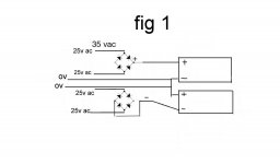
Just curious -- what was it about Fig 1 that made you think that you needed that specifically?
Regards

By the way, if you only have one working bridge on hand, it will work that way, too. There will be folks on here who consider it inferior (from an audiophile viewpoint), but only a few years ago that solution was standard.
Just curious -- what was it about Fig 1 that made you think that you needed that specifically?
Regards
Last edited:
First connect both secondaries in parallel, i.e. connect dot to dot, CT to CT and non-dot to non-dot. Then connect the rectifier's 1st ~ terminal to the dotted secondary terminal and the 2nd one to the non-dotted one. Connect both electrolytics in series, as you've done it yet. Connect the jumper between both 'lytics to the CT's, connect the rectifire's + terminal to the upper 'lytic's + terminal and the rectifier's - terminal to the lower 'lytic's - terminal. Thus the + terminals will show +35 Vdc at idle and the - terminals will show -35 Vdc wrt CT/jumper.
Best regards!
Its wise to sanity-check the winding polarity before paralleling any set of secondary windings. First connect one end of each winding together, leaving the other ends free. Power up and measure the AC volts between the open ends - should be zero, or as close to zero as makes no difference. If you get the polarity wrong this will be obvious. If the windings don't have the same number of turns this will result in a small difference voltage.
If you know the DC resistance of the windings you can estimate whether a small voltage difference is a problem. The circulating current in parallel connection will be the voltage difference you measured divided by the sum of the winding resistances. This should be a lot less than the winding's actual current rating.
thank's guy's for your info after not having much free time to work on amp lately but did a few try's and what ever way i connect i blow Rectifier's (KBPC5010) i ended up using my in inline bulb to limit power on start up and all seem's to power up with out blowing Rectifier's and the power draw when swich on was about 0.47 amps which seem's to be low to damage Rectifier's plus there is a soft start circuit board fitted.
i was able to dismantle the Rectifier and found the diode's inside was 1N1336 but can't seem to find much info on them
i was able to dismantle the Rectifier and found the diode's inside was 1N1336 but can't seem to find much info on them
- Status
- This old topic is closed. If you want to reopen this topic, contact a moderator using the "Report Post" button.
- Home
- Amplifiers
- Power Supplies
- dual secondary transformer connection ?