Does anyone know if there's an LTSpice simulation for a the LT3042 or LT3045?
I am trying to simulate it to regulate from 20v to 15-18v, but I am not familiar with the resistor values you need to use to set the output voltage.
When I input 20v I can't get the simulation to end.
I am trying to simulate it to regulate from 20v to 15-18v, but I am not familiar with the resistor values you need to use to set the output voltage.
When I input 20v I can't get the simulation to end.
At about half way down the product pages under Ltspice simulations are files for 3.8-20V to 3.3V @ 500mA and 3.8-20V to 3.3V @ 200mA.
Here are the links:
https://www.analog.com/media/en/simulation-models/LTspice-demo-circuits/LT3045_DC2491A.asc
https://www.analog.com/media/en/simulation-models/LTspice-demo-circuits/LT3042_DC2246A.asc
You can also find lt3042 and lt3045 demonstration files that you can play with (named 3042.asc and 3045.asc) hidden away in this ltspice windows directory:
"C:\Users\username\Documents\LTspiceXVII\examples\jigs"
Last edited:
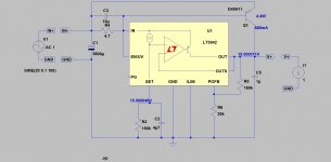
You have B and C shorted on your sim, also you have Vin set at just 5.5 volts. This is a linear reg and so needs at least 18v plus some headroom... which is getting toward maximum ratings for the chip. The voltage setting resistor needs altering to around 221k.
Its not an ideal application for this chip imo (your 18 volts requirement), in fact the data sheet specifies 15 volts as a maximum regulated output.
Its not an ideal application for this chip imo (your 18 volts requirement), in fact the data sheet specifies 15 volts as a maximum regulated output.
> Would this PSRR curve be correct
-196dB is not creditable in a real-world circuit. It "might" happen through lucky cancellation, but don't bet on it. Or expect to real-life measure (or hear!) it.
>100dB is creditable, in a simulation, although real life parasitics will spoil this.
-196dB is not creditable in a real-world circuit. It "might" happen through lucky cancellation, but don't bet on it. Or expect to real-life measure (or hear!) it.
>100dB is creditable, in a simulation, although real life parasitics will spoil this.
euro21,
Can you please upload that asc file?
Thanks!
There it is.
Attachments
There it is.
Thanks.
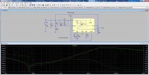
I can't seem to run PSRR and impedance simulations.
Do you know how to set things up for it to run?
Thanks.
I can't seem to run PSRR and impedance simulations.
Do you know how to set things up for it to run?
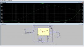
PSRR: run "AC Analysis" with 1V AC input. The result is the output.
Output impedance:
Delete input AC amplitude.
Run "AC Analysis" with 1V AC in current source (Advanced-AC amplitude=1) -as load-.
Plot output voltage. Plot current source current.
Retype V(v+) to V(v+)/I(I1).
Set left vertical axis to linear.
Attachments
Last edited:
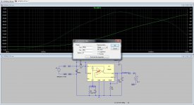
OK, could run the impedance simulation.
Why does it take so long to run? Is there something that could be done for it to run faster?
In other power supply simulations I am doing now the run time is just a few seconds, almost instantly. Why here is different?
Can you feed a negative voltage to have negative output regulator?
Why does it take so long to run? Is there something that could be done for it to run faster?
In other power supply simulations I am doing now the run time is just a few seconds, almost instantly. Why here is different?
Can you feed a negative voltage to have negative output regulator?
Last edited:
Can you feed a negative voltage to have negative output regulator?
Attachments
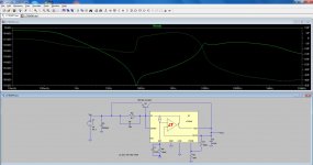
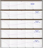
These curves are based on simulations I did, with regulators based on the datasheet.
So the schematics have some more parts than those that are used by DIYINHK.
Perhaps someone can explain me why the differences or the parts missing from the DIYINHK design.
As I didn't quite like the ascending PSRR curve, I am now simulating that adding a CRC filter at the input, with remarkable results.
Attachments

") .
.These curves are based on simulations I did, with regulators based on the datasheet.
So the schematics have some more parts than those that are used by DIYINHK.
Perhaps someone can explain me why the differences or the parts missing from the DIYINHK design.
As I didn't quite like the ascending PSRR curve, I am now simulating that adding a CRC filter at the input, with remarkable results.
BTW, I do not see any kind of load on the first picture?
- Home
- Amplifiers
- Power Supplies
- LT3042/3045 LTSpice simulation