Hello all,
I have a pair of Linkwitz-Riley active crossover boards from XKitz Electronics (unbalanced XOVER-2 version 5.2) that I use to cross my subwoofers and main speakers: linkwitz-riley-2-way-active-crossover
To replace the on-board regulated power supply of both crossovers, I picked up a single ultra low noise 15V regulator board based on the LT3045 regulator chip: LT3045-A
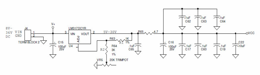
Attached is the schematic of the on-board power supply section of each crossover. I asked XKitz about this and they advised to connect the LT3045 board output to VIN and add a bypass wire across pins 2 and 3 of the LM317DCYR regulator to remove it from the circuit. That works, but they didn't (or couldn't) answer my questions about the rest of the power supply: Shouldn't I remove C15? And what is all the downstream capacitance for? Shouldn't I bypass or remove that? Also, if I simply set the regulated voltage of the LM317DCYR to a higher voltage than the regulated output of the LT3045 board (15V), then wouldn't that have the same result as shorting pin 2 and 3, effectively bypassing the LM317DCYR regulator?
Any insight would be much appreciated!
I have a pair of Linkwitz-Riley active crossover boards from XKitz Electronics (unbalanced XOVER-2 version 5.2) that I use to cross my subwoofers and main speakers: linkwitz-riley-2-way-active-crossover
To replace the on-board regulated power supply of both crossovers, I picked up a single ultra low noise 15V regulator board based on the LT3045 regulator chip: LT3045-A
Attached is the schematic of the on-board power supply section of each crossover. I asked XKitz about this and they advised to connect the LT3045 board output to VIN and add a bypass wire across pins 2 and 3 of the LM317DCYR regulator to remove it from the circuit. That works, but they didn't (or couldn't) answer my questions about the rest of the power supply: Shouldn't I remove C15? And what is all the downstream capacitance for? Shouldn't I bypass or remove that? Also, if I simply set the regulated voltage of the LM317DCYR to a higher voltage than the regulated output of the LT3045 board (15V), then wouldn't that have the same result as shorting pin 2 and 3, effectively bypassing the LM317DCYR regulator?
Any insight would be much appreciated!
Attachments
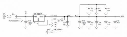
Shouldn't I remove C15? And what is all the downstream capacitance for? Shouldn't I bypass or remove that? Also, if I simply set the regulated voltage of the LM317DCYR to a higher voltage than the regulated output of the LT3045 board (15V), then wouldn't that have the same result as shorting pin 2 and 3, effectively bypassing the LM317DCYR regulator?
Any insight would be much appreciated!
Leaving the 317 in but setting it higher, in effect making it a prereg, is a good solution.
The cap that is there doesn't make much difference but it can't harm, just leave it in.
Jan
It gives the appearance of audiophile design without actually doing too much harm.Abtr said:And what is all the downstream capacitance for?
There is a certain fallacy using multiple bypass caps immediately after any regulator -- they all have different impedance/phase curves and relationships which can compete with each other, and badly. (Not an original thought to me, Several folks have pointed this out.)
Use the recommended electrolytic after the regulator -- with a low dropout regulator this capacitor is part of the feedback loop and it has to be specified for the application. You can use ceramic bypass at or as close as possible to the chips being powered by the supply as they themselves are decoupled by trace resistance and inductance.
Use the recommended electrolytic after the regulator -- with a low dropout regulator this capacitor is part of the feedback loop and it has to be specified for the application. You can use ceramic bypass at or as close as possible to the chips being powered by the supply as they themselves are decoupled by trace resistance and inductance.
Some of the regulator (and opamp) manufacturers go into great detail on what works and what doesn't in the app notes in their datasheets.
Many eBay designers don't appear to read them.
But at least XKitz put R65 in to decouple C65 from the rest of the capacitor bank. (I'd guess that accounts for DF96's "without actually doing too much harm".)
Many eBay designers don't appear to read them.
But at least XKitz put R65 in to decouple C65 from the rest of the capacitor bank. (I'd guess that accounts for DF96's "without actually doing too much harm".)
OK, thanks for the replies! I'm less worried now about all those caps.
According to the data sheet the LT3045 is stable with a minimum 10µF ceramic output capacitor with an ESR below 20mΩ and an ESL below 2nH (see data-sheet). I assume this requirement has been met in the implementation on the LT3045-A regulator board. The data sheet further states that large load transients require larger output capacitance to limit peak voltage transients.
So the large electrolytes and extra (decoupled) downstream capacitance on the crossover boards should not be a problem, unless different caps interact or compete in a bad way. The latter doesn't seem to be the case which I base on subjectively improved sound quality with the new LT3045-A regulator and LM317 out of the circuit..
...unless different caps interact or compete in a bad way...
They can. Often do. This is not well understood by cap-stackers.
All "capacitors" are also inductors, above some high frequency.
Two "caps" in parallel is really 2 C, 2 L (and some R). The L of one resonates with the C of the other and instead of a low impedance we get a high impedance at some narrow band of high frequencies.
Here is an example from tube-amps. 40uFd bulk-cap with 0.1uFd "bypass cap". Parasitic L and R taken from datasheets. You see the Impedance "Z" is dropping across the audio band, as expected. Ideally it would hold the same slope to zero impedance at infinite frequency. Or just bottom-out and rise again, which can be fine also. But instead it peaks to a very high Z, maybe 43 ohms, at 350kHz. Tubes can have gain at 350kHz, transistor can have more gain. The unexpected rise of rail Z at high frequency can induce leak-back through the rail. It can de-stabilize an opamp. (It could mess-up the tuning of a tube IF strip.) Note also the radical change of phase-shift "P", working with or against the amplifier's own phase shift.
It happens that 43 ohms is still a "small" value in tube-work, and this Z zig-zag is not likely a problem. It would be worse if the 40uFd electrolytic had lower than 0.5r of ESR, because 0.5r starts to spoil the resonances. It would be a bit better with a resistive load, however in hi-fi we often over-over-size the caps far bigger than the DC load needs so the DC load does little for damping. (Even less if the load is a lot of current-limited paths, as in many ICs and fancy discretes.)
Attachments
Last edited:
I removed C15 and C65 from the crossover boards but I left the stack after R65 intact. I may remove the 10uF and/or .1uF caps and/or replace C16 by an aluminum propylen type (Kemet A750). I'll ask Xkitz about the exact purpose.They can. Often do. This is not well understood by cap-stackers. ......unless different caps interact or compete in a bad way....
Meanwhile, it's amazing what a voltage regulator can do for a preamp/buffer (which is how the crossover functions in my system) in terms of sound quality!
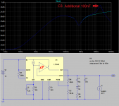
I thought it might be instructive to put into a picture what PRR and others have related. C3 is "parameter selected" for 1pF or 100nF. All the other values are per the datasheet. (with a little parasitic inductance thrown in for good measure). The dark blue line shows the effect of the additional capacitor -- an additional impedance peak with Q~=2.9, so phase margin is only 18 degrees.
Attachments
You may want to hunt down the crossover's obvious PSRR problem then, in case you're not just fooling yourself that is. I see it seems to be a single supply job - how are they generating their Vcc/2 reference? That would be my first suspect. The circuitry at the input looks like maybe a cap multiplier and some passive RC, but I don't see where the rail splitting occurs. Maybe it involves C20? If the circuitry is inverting like I suspect it is, check where the noninverting inputs go.Meanwhile, it's amazing what a voltage regulator can do for a preamp/buffer (which is how the crossover functions in my system) in terms of sound quality!
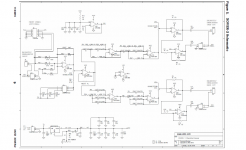
Attached is the complete schematic (also see user manual)..You may want to hunt down the crossover's obvious PSRR problem then, in case you're not just fooling yourself that is. I see it seems to be a single supply job - how are they generating their Vcc/2 reference? That would be my first suspect. The circuitry at the input looks like maybe a cap multiplier and some passive RC, but I don't see where the rail splitting occurs. Maybe it involves C20? If the circuitry is inverting like I suspect it is, check where the noninverting inputs go.
Attachments
Last edited:
Another possible reason to avoid generalized capacitor yanking -- at least two of those 1uF jobbies, C63 and C64, are local supply bypassing for a quad opamp.
Since this piece is single supply, I'm surprised any *interest in capacitors* doesn't begin with the coupling caps.
Cheers, Rick
Edit: oooh, yaay, complete schematic ..
Since this piece is single supply, I'm surprised any *interest in capacitors* doesn't begin with the coupling caps.
Cheers, Rick
Edit: oooh, yaay, complete schematic ..
It seems something was upsetting the stability of the LM317 regulators. The much improved sound quality with LM317 bypassed is compared to the sound quality in the situation with the on-board power supply section intact and output voltage set to 15V (which is fixed and can't be adjusted in version 5.1 of the crossover boards which I use) while being fed by the 15V output of the LT3045-A board, which in turn was fed by a 17.5V LPS.
The idea was that without headroom for the LM317 to regulate the voltage (15V in and 15V out) it would be effectively out of the circuit. Apparently it doesn't work that way and shorting pins 2 and 3 results in a much better sounding crossover.
To be sure I ordered another pair of crossover boards. I'll set them to 15V and try them without LT3045-A and feed them directly with the 17.5V LPS. I used them this way in the past and although it was an improvement over the built-in crossovers of my subs I can't remember them sounding as good as they do now. But we'll see..
I thought it might be instructive to put into a picture what PRR and others have related. C3 is "parameter selected" for 1pF or 100nF. All the other values are per the datasheet. (with a little parasitic inductance thrown in for good measure). The dark blue line shows the effect of the additional capacitor -- an additional impedance peak with Q~=2.9, so phase margin is only 18 degrees.
Very instructive Jack!
Jan
I received the new crossover boards and fed them directly with the 17.5V LPS. The sonic difference is evident. The modified boards with LT3045 regulator and LM317 out of the way perform much better. The improvement is not subtle. The modified boards clearly sound more refined and less fatiguing.
I might make some ADC captures in Audacity and compute an FFT of the difference..
I might make some ADC captures in Audacity and compute an FFT of the difference..
Last edited:
So I asked Xkitz about the function of the parallel capacitors after R65. Still no reply. I guess C16 may be there for better transient response and the 0.1uF caps and C22 may lower overall ESR. I wonder if I can replace them by a single low ESR cap.
Given that different parallel output caps can oscillate and affect sound quality, could it be that the capacitor stack was designed for a specific audible effect (possibly related to the LM317 voltage regulator)?
Given that different parallel output caps can oscillate and affect sound quality, could it be that the capacitor stack was designed for a specific audible effect (possibly related to the LM317 voltage regulator)?
Well, it's only 4.7 Ohm..R65 is an abomination. First you invest in a low Zout regulator and then you throw it away with R65.
The idea was that without headroom for the LM317 to regulate the voltage (15V in and 15V out) it would be effectively out of the circuit. Apparently it doesn't work that way and shorting pins 2 and 3 results in a much better sounding crossover.
That won't work well because an LM317 has a dropout voltage, so you still get a few volts of drop across the LM317 (precise value depending on current, temperature and what not). The reason Jan recommended it is that he was under the false impression that you would use the LM317 as a preregulator (unregulated supply - LM317 set to 16 V or 17 V or so - LT3045 set to 15 V rather than unregulated supply - LT3045 set to 15 V - LM317 set to 15 V).
- Status
- This old topic is closed. If you want to reopen this topic, contact a moderator using the "Report Post" button.
- Home
- Amplifiers
- Power Supplies
- Voltage regulator bypass questions