R65 is an abomination. First you invest in a low Zout regulator and then you throw it away with R65.
Jan
Using an LM317 or 78XX, it can be a simple way to get rid of regulator noise though, if the decoupling capacitance is large enough.
Okay, so do you think I could/should bypass R65 (especially with the LM317 regulator circuit replaced by the LT3045 board)?R65 is an abomination. First you invest in a low Zout regulator and then you throw it away with R65.
Jan
I did some blind listening tests with the crossover power section based on LT3045 versus LM317 and identified the correct chip 7 times out of 7 tests (source was an RME ADI-2 DAC). I really wonder if I can further improve the original power supply of the crossover boards:
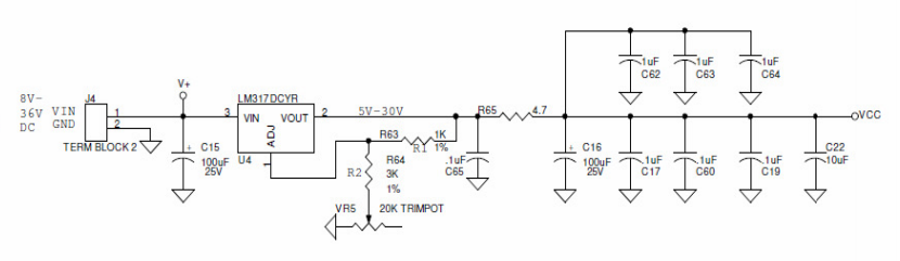
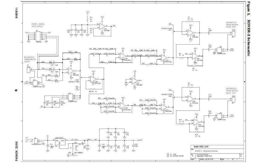
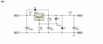
I already removed C15 and C65 and shorted pin 2 and 3 of the LM317 regulator for use with the LT3045 regulator board. Possibly R65 can be bypassed and the other caps may be removed or be replaced by a single cap. Each crossover board has three OPA1654 quad opamps to feed:
Any insight will (again) be greatly appreciated!")
I already removed C15 and C65 and shorted pin 2 and 3 of the LM317 regulator for use with the LT3045 regulator board. Possibly R65 can be bypassed and the other caps may be removed or be replaced by a single cap. Each crossover board has three OPA1654 quad opamps to feed:
Any insight will (again) be greatly appreciated!
Last edited:
That won't work well because an LM317 has a dropout voltage, so you still get a few volts of drop across the LM317 (precise value depending on current, temperature and what not). The reason Jan recommended it is that he was under the false impression that you would use the LM317 as a preregulator (unregulated supply - LM317 set to 16 V or 17 V or so - LT3045 set to 15 V rather than unregulated supply - LT3045 set to 15 V - LM317 set to 15 V).
I think what would happen if the '317 runs out of headroom is that the pass transistor will be driven fully open. So effectively you have a low impedance, 0.3V or so 'battery' in the line path. Should not do much harm, but no good either.
Jan
At page 4 of https://www.st.com/resource/en/datasheet/lm317.pdf you can see the internal schematic of an LM317 and at page 8 a graph of the dropout voltage versus temperature with current as a parameter. It has a Darlington NPN output stage, so the voltage drop is around 1.5 V at low currents (20 mA) at room temperature. At 1 A it is around 2 V. In any case, we agree that it doesn't do any good when it is connected this way.
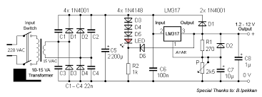
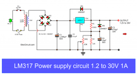
It's a petty Xkitz don't respond to my query about the series resistor and output caps configuration. I found many LM317 regulator diagrams with different (parallel) caps (see e.g. attached examples), but none have a series resistor.
I may just try bypassing R65 and remove all output caps (except perhaps C16) for use with the LT3045 board and then see what happens..
I may just try bypassing R65 and remove all output caps (except perhaps C16) for use with the LT3045 board and then see what happens..
Attachments

OK, thanks. I'll try bypassing R65. Can you elaborate on what might be the idea behind r65 (noise reduction)? And what about the caps after R65? Should I remove them for the LT3045 regulator board?Throw away R65. It's a misguided attempt to improve' something the wrong way.
Jan
OK, thanks. I'll try bypassing R65. Can you elaborate on what might be the idea behind r65 (noise reduction)? And what about the caps after R65? Should I remove them for the LT3045 regulator board?
Someone *probably* thought that he/she could lower the noise after the regulator further. But trying that it would completely swamp the low output impedance of the regulator. Like, you have a reg with less than 1 ohm Zout, which means the output voltage it is rock-steady with all the variations in load current that happen while amplifying a signal.
Now you place a Very Large resistor in series, wasn't it 4.7 ohms? So if the load current varies, so does the supply voltage, undoing what the regulator was for in the first place.
Then you place some capacitance after that 4.7 ohms. Tat helps for low output impedance but such a cap has easily a larger ESR than the regulator Zout, and especially at higher frequencies ruins it because of parasitic inductance.
Such a capacitor after a regulator (without the R) is not there to lower the regulator Zout but only for stability; the regulator is 'better' than that cap anyway.
So such things as R65 + cap are done by people with enough knowledge to be dangerous ;-)
Jan
Last edited:
Thank you! One more question. In addition to bypassing R65 I'm thinking about removing the caps after R65 and replace them with a single Kemet A750 cap (aluminum propylen) of several hundred uF to improve transient response. Would that be a good idea? Note that the LT3045 regulator board is connected through 10cm long wires to the crossover board's VIN connectors.Someone *probably* thought that he/she could lower the noise after the regulator further. But trying that it would completely swamp the low output impedance of the regulator. Like, you have a reg with less than 1 ohm Zout, which means the output voltage it is rock-steady with all the variations in load current that happen while amplifying a signal.
Now you place a Very Large resistor in series, wasn't it 4.7 ohms? So if the load current varies, so does the supply voltage, undoing what the regulator was for in the first place.
Then you place some capacitance after that 4.7 ohms. Tat helps for low output impedance but such a cap has easily a larger ESR than the regulator Zout, and especially at higher frequencies ruins it because of parasitic inductance.
Such a capacitor after a regulator (without the R) is not there to lower the regulator Zout but only for stability; the regulator is 'better' than that cap anyway.
So such things as R65 + cap are done by people with enough knowledge to be dangerous ;-)
Jan
So I bypassed R65 on both crossover boards and it's a major upgrade. Thanks again! It's now easy to 'listen into the music'. Different instruments/tracks can be easily distinguished and overall sound is more alive and involving.
I think I'll leave the output caps (C16 and parallel capacitors) in place for now. I suppose they can't do much (if any) harm in a strictly analogue audio application.
Any thoughts will as always be much appreciated!
I think I'll leave the output caps (C16 and parallel capacitors) in place for now. I suppose they can't do much (if any) harm in a strictly analogue audio application.
Any thoughts will as always be much appreciated!

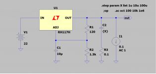
I thought it might be instructive to put into a picture what PRR and others have related. C3 is "parameter selected" for 1pF or 100nF. All the other values are per the datasheet. (with a little parasitic inductance thrown in for good measure). The dark blue line shows the effect of the additional capacitor -- an additional impedance peak with Q~=2.9, so phase margin is only 18 degrees.
Can you upload the asc file for this simulation?
Thanks!
Can you upload the asc file for this simulation?
Thanks!
I think this is the one.
Attachments
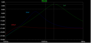
I finally received an answer from Xkitz to my question about the function of the capacitor stack after R65: Can I replace it by a single low ESR cap? See:
Their answer: "You could try this, but it will likely result in higher noise floor. Parallel caps of different values filter different frequency ranges of noise. This is recommended by the op amp mfgr, TI. It will not oscillate in a power supply application."
They refer to OPA1654 in the diagram below:
Nothing about this in the OPA1654/1652 datasheets..
Last edited:
Can I replace it by a single low ESR cap? "You could try this, but it will likely result in higher noise floor.
Parallel caps of different values filter different frequency ranges of noise. This is recommended by the
op amp mfgr, TI. It will not oscillate in a power supply application."
TI recommends between 0uF and 1uF for the LM317 output capacitor, and 10uF for the ADJ terminal.
Capacitors after the series resistor R65 will not affect the regulator's transient response, but they can
filter some HF noise. However the parallel capacitor combination likely has an erratic combined impedance,
due to their parasitics. The 4.7R series resistor will degrade the performance of the LM317.
Last edited:
TI recommends between 0uF and 1uF for the LM317 output capacitor, and 10uF for the ADJ terminal.
Where does TI recommend that? The LM317 will not be stable without an output capacitor, and a 100uF aluminum electrolytic will work fine.
A capacitor on the ADJ pin reduces noise at the expense of transient response. (This TI has pointed out .)
Attachments
I received a further reply from Xkitz:
"Decoupling caps are required to be placed near every op amp in the system. As I mentioned earlier, different values filter different frequency ranges of noise. The parallel .1uF, 1uF, and 10uF was a recommendation from an old Burr-Brown app note (which I can't find now). Their measurements indicated this resulted in the lowest noise on the outputs of the op amps."
According to the OPA1652/1654 datasheet (p. 24: “applications with noisy or high-impedance power supplies require [low ESR ceramic] decoupling capacitors close to the device pins. In most cases, 0.1-µF capacitors are adequate.” See: http://www.ti.com/lit/ds/symlink/opa1652.pdf)
So with the ultra low noise and low impedance LT3045 based power supply, the decoupling caps at the op amps may not be necessary..
- Status
- This old topic is closed. If you want to reopen this topic, contact a moderator using the "Report Post" button.
- Home
- Amplifiers
- Power Supplies
- Voltage regulator bypass questions