It would make sense to define what is meant by ground. There is safety ground (PE), audio GND and possible a DC GND too which might not need to be switched when switching audio GND. Please note that "-" is not GND.
Audio GND is not always connected to PE. In anglosaxon countries the low voltage or audio GND is almost always connected to PE. This is very debatable but discussion leads to GND/PE wars very soon") Using PE on every device means a ground loop for sure when for instance a tuner is used with a coax cable that has GND elsewhere connected to PE.
Using PE on every device means a ground loop for sure when for instance a tuner is used with a coax cable that has GND elsewhere connected to PE.
PE always is required for safety when metal cases are used. Never switch PE!!! Personally I only connect PE to power amplifiers casings but that is up to me. There is only one person in this household. When SMPS are used one can often not get away with not using PE (depending on the class) as filters use PE to get rid of noise and stuff. If SMPS are designed for PE use then PE must be used. If they are "floating" then PE can be omitted. PE then still needs to be connected to the metal casing. When no connection is made between GND and PE in such cases connecting PE to the casing has the benefit of safety and no negative side effects.
If audio GND is meant: these can be switched but please note that it depends of the situation and a negative side effect may be audible clicks in audio because of potential differences. To solve this a resistor can be used to give a reference to audio GND. This will solve the clicks and still reaches the set goal.
In special cases like coax SPDIF switching GND of the various sources makes things better as otherwise long open unused cables may be connected when another source is selected. The open cables may serve as an unwanted antenna.
Audio GND is not always connected to PE. In anglosaxon countries the low voltage or audio GND is almost always connected to PE. This is very debatable but discussion leads to GND/PE wars very soon
Using PE on every device means a ground loop for sure when for instance a tuner is used with a coax cable that has GND elsewhere connected to PE.PE always is required for safety when metal cases are used. Never switch PE!!! Personally I only connect PE to power amplifiers casings but that is up to me. There is only one person in this household. When SMPS are used one can often not get away with not using PE (depending on the class) as filters use PE to get rid of noise and stuff. If SMPS are designed for PE use then PE must be used. If they are "floating" then PE can be omitted. PE then still needs to be connected to the metal casing. When no connection is made between GND and PE in such cases connecting PE to the casing has the benefit of safety and no negative side effects.
If audio GND is meant: these can be switched but please note that it depends of the situation and a negative side effect may be audible clicks in audio because of potential differences. To solve this a resistor can be used to give a reference to audio GND. This will solve the clicks and still reaches the set goal.
In special cases like coax SPDIF switching GND of the various sources makes things better as otherwise long open unused cables may be connected when another source is selected. The open cables may serve as an unwanted antenna.
Last edited:
Hi Jean-Paul,It would make sense to define what is meant by ground. There is safety ground (PE), audio GND and possible a DC GND too.
Audio GND is not always connected to PE. In anglosaxon countries the low voltage or audio GND is almost always connected to PE. This is very debatable but discussion leads to GND wars very soon
PE always is required for safety when metal cases are used. Never switch PE!!! Personally I only connect PE to power amplifiers casings but that is up to me. There is only one person in this household.
If audio GND is meant: these can be switched but please note that it depends of the situation and a negative side effect may be audible clicks in audio because of potential differences. To solve this a resistor can be used to give a reference to audio GND. This will solve the clicks.
In special cases like coax SPDIF switching GND of the various sources makes things better as otherwise long open unused cables may be connected when another source is selected. The open cables may serve as an unwanted antenna.
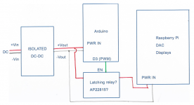
No audio switching here, audio selector will be another board, not this one. No PE either: I'll be using DC in, to avoid mains handling at all costs. Isolated DC-DC modules to get 5V and ±12V after the DC in. These switches are meant for unused power rails after the isolation DC-DC. Thus, Ground in these switches refer to the ground coming out of the DC-DC conversions. Unless I'm missing something.
Thank you
If you switch DC sources that are symmetrical you should not switch GND as things can go wrong when one of both voltages may be up earlier than the other one (or the GND misfiring). This may lead to unwanted effects and/or large DC offsets/pops further in the chain.
Secondly you should switch the + and - only with semiconductor switches. Real switches or relay contacts will burn in fast when switching DC. This is normal, one of the reasons to switch AC instead of DC. Nowadays chinese engineers seem to forget this as I often see DC switching with mechanical switches. The switches will fail sooner than one thinks.
But I may misunderstand you, that is why schematics are invented. A drawing says way more than words. Anyway there are several reasons to switch mains voltages so AC switching is preferred. You will have the benefit of being sure things are truly powered off when you leave your home. Any detrimental power up/down phenomena when switching mains voltages can be solved with anti-parallel diodes, muting relays and such.
If you persist in switching DC then semiconductor switches or logic level MOSFETs are almost mandatory.
Last edited:
Relays and switches have switched DC for decades, even at high currents. While most things are going electronic, you will probably still find 40A relays in your car. My Old VW used an 80A relay for the fuel pump. If you use mechanical switching with switches or relays, just over-engineer it. Switching 3A? use a 10A switch. Simple.
I even use these to switch 400VDC. Never had a failure or arc. Relay Series FRC1, Relay Series FRC1 - Forward Industrial Co.
I even use these to switch 400VDC. Never had a failure or arc. Relay Series FRC1, Relay Series FRC1 - Forward Industrial Co.
Last edited:
Very good point. I was already convinced to leave grounds alone anyway, so only aim for switching DC rails.If you switch DC sources that are symmetrical you should not switch GND as things can go wrong when one of both voltages may be up earlier than the other one (or the GND misfiring). This may lead to unwanted effects and/or large DC offsets/pops further in the chain.
Fair enough. I will try to do a basic scheme later tonight.But I may misunderstand you, that is why schematics are invented. A drawing says way more than words.
Again, no mains here, this is all DC from a laptop charger.You will have the benefit of being sure things are truly powered off when you leave your home. Any detrimental power up/down phenomena when switching mains voltages can be solved with anti-parallel diodes, muting relays and such.
Relays and switches have switched DC for decades, even at high currents. While most things are going electronic, you will probably still find 40A relays in your car. My Old VW used an 80A relay for the fuel pump. If you use mechanical switching with switches or relays, just over-engineer it. Switching 3A? use a 10A switch. Simple.
I even use these to switch 400VDC. Never had a failure or arc. Relay Series FRC1, Relay Series FRC1 - Forward Industrial Co.
In a car there is no AC AFAIK so not much choice but overdimensioning. There is space enough to do so. In audio equipment space is an issue. Besides that there is AC available.
That things are done for decades does not say much. People use guns to kill other people for more than 100 years. It does not make it less wrong.
Please note that in cars capacitive loads do not occur often contrary to power supplies and other circuits in audio. Capacitive loads kill contacts.
When there is choice always choose AC over DC. Arcing IS a phenomenon that is more prominent when switching DC.
PS the relays you use are rated for 75V Max. Using these to switch 400V is plain stupid.
Last edited:
Hi, I don’t know who that Greta is, but reasons explained in first and 7th post, more specifically
On 20 August 2018, during an exceptionally hot and dry summer, a 15-year-old Swedish girl with Asperger's called Greta Thunberg began sitting in front of the Swedish parliament every day until the 2018 Swedish elections with a sign saying Skolstrejk for klimatet (School strike for climate). Since the elections, she only protests each Friday, and she intends to keep doing so until Sweden fully meets the Paris agreement.
Other school children and adults followed her example. Some protest every Friday, others only occasionally. The greatest protests so far were in the week from 20 to 27 September this year, with about 7 million people participating worldwide and with protests on all continents. The next mass event is planned for 29 November and 6 December.
Greta Thunberg (@GretaThunberg) | Twitter
In a car there is no AC AFAIK so not much choice but overdimensioning. There is space enough to do so. In audio equipment space is an issue. Besides that there is AC available.
That things are done for decades does not say much. People use guns to kill other people for more than 100 years. It does not make it less wrong.
Please note that in cars capacitive loads do not occur often contrary to power supplies and other circuits in audio. Capacitive loads kill contacts.
When there is choice always choose AC over DC. Arcing IS a phenomenon that is more prominent when switching DC.
PS the relays you use are rated for 75V Max. Using these to switch 400V is plain stupid.
Capacitive load are hard on contact, agreed. Arcing is more prevalent with DC because there is no zero crossing, agreed.
Ratings are not for safety, they are for lawsuit protection IMHO. I would not switch 400VDC at 40A with these of course, but for low current they have proved to be fine. Besides the fact that even if it did arc over the worst thing to happen would be the amp not turning off. If it arced to ground the fuse would blow. There is NO shock hazzard whatsoever.
I also would not sell an amp to someone else that used one in this capacity unless they were ok with it. The customer can decide if they want to waste 100's of dollars, right?
All the DC vs AC relays is super interesting, thank you.
I would like to come back to the finding in post 20 of AP22815BWT-7 power switch as a candidate replacement of a relay:
I would like to come back to the finding in post 20 of AP22815BWT-7 power switch as a candidate replacement of a relay:
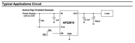
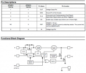
Thank you so muchI might've found a way to avoid relays, using a power switch per each optional rail, at least for the 5V@3A. For instance, AP22815BWT-7. If I'm not mistaken this chip accepts a Input Voltage Range of 3.0V ~ 5.5V, and has an Enable input that acts as the switcher. It even has Overcurrent, Short-Circuit and Thermal Protection, Output Reverse-Voltage/Current Protection, Undervoltage Lockout etc. The EN feature is described as:
ON/OFF Input Operator
The EN input allows the output current to be switched on and off using a GPIO compatible input. The high signal (switch on) must be at least 1.2V and the low signal (switch off) no higher than 0.4V. This pin should not be left floating. It is advisable to hold the EN signal low when applying or removing power
Would anyone here please confirm this is a valid approach or I'm completely nuts? If this is valid, I'd need to find a similar product for +12V and for -12V rails.
Attachments
Jean-Paul,
Here's the drawing. I don't think we need a super details proper schematics at this points.
Please see my previous message with a possible alternative to latching relays, using the AP22815BWT-7 power switch.
Thank you
jean-paul said:A drawing says way more than words.
I will try to do a basic scheme later tonight.
Here's the drawing. I don't think we need a super details proper schematics at this points.
Please see my previous message with a possible alternative to latching relays, using the AP22815BWT-7 power switch.
Thank you
Attachments
Main "Isolated DC-DC" power unit will be on all time? So I dont see reason to use relay, but you can use just mosfet (for example - P-mosfet). May be there is some low-level (logic-level), I don't know exact popular part number right now. AO3401?
Hi, yes, isolated DC-DC will be ON all the time. I will investigate on using mosfets, thank you. Any circuit you know I can look at?
Hi again,
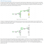
I'm just reading about using transistors. Apparently, the proper way to triggering a power circuit on/off through an Arduino signal is by using a P-Channel MOSFET as the switching transistor with a NPN transistor driver for that P-Channel. See NPN-PNP Driver Example section, from the baldengineer site, where I got the attachment capture from.
Also learnt from baldengineer that in theory there are off-the-shelf components called power switch or load switch, which basically would be ICs with the P-Channel MOSFET and a built-in NPN driver. Haven't found any in mouser though (or if I did, when reading the datasheet, I cannot find the explicit reference to the driver).
Also was having a look at this video Using PNP Bipolar Transistors with Arduino, from min 8:15 you'll see 3 circuits for the same purpose (one as the attachment, 2 a bit more complex, using Darlingtons).
I will keep reading.
Thank you again
Attachments
- Status
- This old topic is closed. If you want to reopen this topic, contact a moderator using the "Report Post" button.
- Home
- Amplifiers
- Power Supplies
- Power unused circuits off: should power grounds be switched?