In this application note from National Semi, look at the opamp power supply buffers that feed the RIAA preamp. Joe Curcio showed this basic opamp buffer first in issue two-1985 of The Audio Amateur in his Daniel tube preamp. I have not seen any discussion of this power supply buffer that is supposed to have low impedance over the audio bandwidth. Has anyone tried this buffer design, and if so how did it perform?
Attachments
Have not tried this particular scheme. It should work. I suspect it is also a ploy to sell more LME49710s. Many other chips could do the same thing.
That this follows is not "clear" to me. A sufficiently complex and sophisticated chip should ignore the crap and sag on its rails. And if Z is "low enough", it merely needs to stay low, need not be flat.
if one envisions an audio amplifier as a device that modulates the power supply current into the load in direct response to the input signal, it is clear that the power supply rails must present a low and more importantly flat impedance across the audio bandwidth to preserve the audible spectral balance and overall integrity of the input signal.
That this follows is not "clear" to me. A sufficiently complex and sophisticated chip should ignore the crap and sag on its rails. And if Z is "low enough", it merely needs to stay low, need not be flat.
how did it perform?
Built the Curcio phono stage in the 80s, shortly after the AA article. Hated it in general. Hated it a bit less without the opamp noise cleaners. His idea was lifted off the ARC SP10 which i also built and although the phono section was better, the opamp cleaners addition did not bring benefits for me, on the contrary.
Same with the app note circuit - IMO it thins out and bleaches the sound. Yes, each amplification stage should get their own regulated power supply, but not following this topology.
A straight connection directly to an undamped 1µF capacitor sounds dangerous for the vast majority of opamps.
Here, the opamp is operated at a gain of ~10, which may ease matters, but that would still be insurmountable for the vast majority of the chips.
Some opamps are known for their tolerance: for example the LF356 tolerates 10nF.
Maybe, as an insider, Mr Curcio knows certain things we don't, but in the datasheet, there is nothing hinting at that:
I will make a little test, to see how the output impedance behaves with a 1µF load
Here, the opamp is operated at a gain of ~10, which may ease matters, but that would still be insurmountable for the vast majority of the chips.
Some opamps are known for their tolerance: for example the LF356 tolerates 10nF.
Maybe, as an insider, Mr Curcio knows certain things we don't, but in the datasheet, there is nothing hinting at that:
I don't have 49710s handy, but I have LM4562s, and they look very similar.The LME49710 is a high-speed op amp with excellent phase margin and stability. Capacitive loads up to 100pF
will cause little change in the phase characteristics of the amplifiers and are therefore allowable.
Capacitive loads greater than 100pF must be isolated from the output. The most straight forward way to do this is
to put a resistor in series with the output. This resistor will also prevent excess power dissipation if the output is
accidentally shorted.
I will make a little test, to see how the output impedance behaves with a 1µF load
According to the own model provided by NS/TI, this arrangement does nasty things.
The output impedance shows a peak at ~400kHz, something less than ideal for a supposedly perfect bypass:
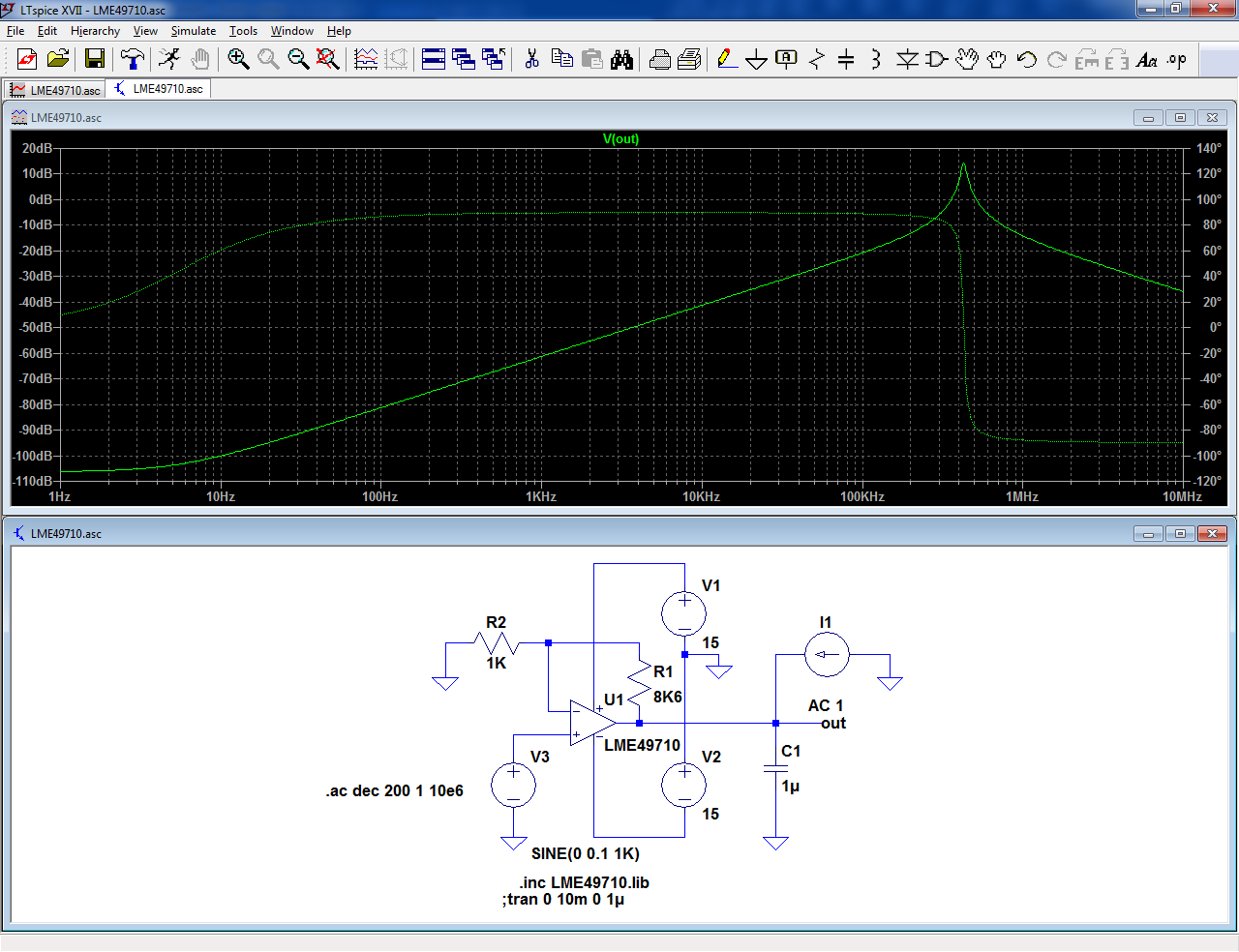
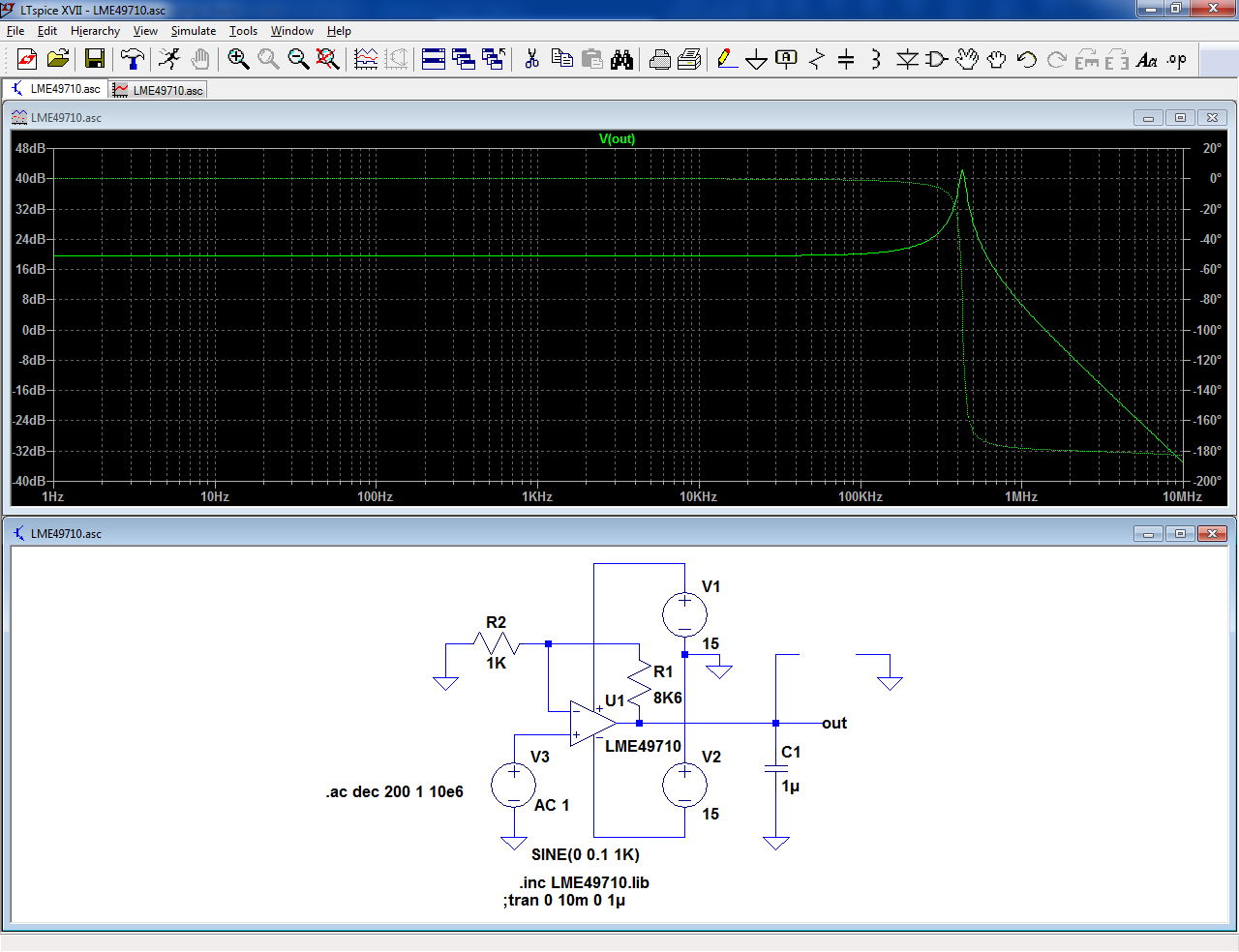
Looking at it the other way, the peak is also present in the gain: more than 20dB excess, which is going to corrupt the carefully LP-filtered input:

The output impedance shows a peak at ~400kHz, something less than ideal for a supposedly perfect bypass:
Looking at it the other way, the peak is also present in the gain: more than 20dB excess, which is going to corrupt the carefully LP-filtered input:
Attachments

Built the Curcio phono stage in the 80s, shortly after the AA article. Hated it in general. Hated it a bit less without the opamp noise cleaners. His idea was lifted off the ARC SP10 which i also built and although the phono section was better, the opamp cleaners addition did not bring benefits for me, on the contrary.
Same with the app note circuit - IMO it thins out and bleaches the sound. Yes, each amplification stage should get their own regulated power supply, but not following this topology.
Thanks for that information, it's very helpful. Now I know how they sound.
Curcio is still around and selling the Daniel tube preamp. Here is the circuit with the buffers that have a series pass transistor as part of the output. This design does not have a cap on the output of the op amp.
https://www.curcioaudio.com/d2phsch.gif
According to the own model provided by NS/TI, this arrangement does nasty things.
The output impedance shows a peak at ~400kHz, something less than ideal for a supposedly perfect bypass:

Looking at it the other way, the peak is also present in the gain: more than 20dB excess, which is going to corrupt the carefully LP-filtered input:
Thanks for the data Elvee!
...output impedance shows a peak at ~400kHz
This after the paper states "the power supply rails must present a low and more importantly flat impedance across the audio bandwidth" ???
Instead we get 1 milliOhm at 1kHz, 10m at 10k, 0.1r at 100kHz ???
In fact it is a 0.15uH(?) inductor !!!
I agree this is "low". Sure aint "flat".
1 Ohm in series would swamp the <20mOhm impedance in the audio band.
I have made a real-world test, not on the LME49710, since I don't have any sample in my drawers, but on the LM4562 which looks like an almost perfect clone, based on the characteristics.
The pathological behavior observed in sim was present, but to a lesser degree: the resonance peak was around 250kHz, against 400kHz in the sim, and the peak magnitude, both for gain and impedance was ~10dB, against 20dB in sim.
I made the test on a breadboard, and the 1µF capacitor was an ordinary 63V metallized mylar cap, which could explain the differences in part or totality: the breadboard adds contact resistances and parasitic inductances, and the cap is not the ideal one of the sim.
It could be that with a good PCB and a PP plain foil cap, reality and sim would converge -or not-.
Anyway, even if this expedient looks rather harmless, it is probably better to stick to more conventional solutions: monolithic voltage regulators are designed for the job, in particular capacitive loads, and they can be quite good regarding noise.
The LME is in principle better in this respect, but since it necessary to attenuate the reference voltage to reamplify it 10x afterwards, it mostly negates this superiority.
Initially, I made the test with ground-referenced inputs, but later I realized that using the opamp in a single-ended, regulator fashion could make a difference, and I modified the test setup accordingly, but no significant change was visible
Yes, there are many ways to shave a cat, and this one may not be best.
_I_ like a big capacitor(s) right ON the rail. Most chips (and many discretes) have falling PSRR at high frequency. Caps filter better the higher up you go.
If stuff stays class-A and modest power, I've had happiness with simple C-R-C-R-C filtering. Big caps are cheap now. Set the main corner far below the audio band and 120Hz will be teeny; also wall-voltage variations are reduced to sub-sub-sonic bobble instead of thumps. (No thump if you favor regulated bias reference or bipolar supply.)
Yes, there are many ways to shave a cat, and this one may not be best.
_I_ like a big capacitor(s) right ON the rail. Most chips (and many discretes) have falling PSRR at high frequency. Caps filter better the higher up you go.
If stuff stays class-A and modest power, I've had happiness with simple C-R-C-R-C filtering. Big caps are cheap now. Set the main corner far below the audio band and 120Hz will be teeny; also wall-voltage variations are reduced to sub-sub-sonic bobble instead of thumps. (No thump if you favor regulated bias reference or bipolar supply.)
How big a cap are you using on the rails?
I also like RC filters. I use one or two sections of them before the regulator to try and lower the ripple and harmonics as much as possible in the space I have. No need for the error amp to deal with all this stuff if we can lower it before it gets there.
- Status
- This old topic is closed. If you want to reopen this topic, contact a moderator using the "Report Post" button.
- Home
- Amplifiers
- Power Supplies
- Opamps as low Z buffers