Elvee,
I am slowly reading your whole D-Noizator thread, and I have found it very exciting.
Particularly when you added the NoNoiser to the game, which seems to be a very interesting supply. In fact I am considering using it for a Luxman RIAA clone I'm building, instead of the Jung/Didden superregulator.
I'm still in page 7, so there might still be more surprises and things to learn.
Another interesting thing was the "discrete superregulator"
Just for fun: a superreg with <12 discretes??! ?! ?
Would that be a better specced option than Kit Ryan's for high voltage/low current?
Besides the specs I would have to weigh down the higher number of parts over the Kit Ryan's version you simmed for me, which is the one I'm planning to build.
But I would be ready to build both and see if your LV discrete design may sound better.
In any case, both your designs look very good and promising. Congratulations.
Last edited:
At least, that's a job ideally suited for the No- or De-noiser: depending on the exact configuration, the PSRR could be near 0dB (or even +xdB's in poor designs), and a very good regulator makes sense, unlike the signal stages of a PA, which should tolerate some amount of ripple without too much troubleParticularly when you added the NoNoiser to the game, which seems to be a very interesting supply. In fact I am considering using it for a Luxman RIAA clone I'm building,
It does have significantly better specs, but is also more complex (relatively), but being discrete can be translated for any output voltage with suitable parts.Another interesting thing was the "discrete superregulator"
Just for fun: a superreg with <12 discretes??! ?! ?
Would that be a better specced option than Kit Ryan's for high voltage/low current?
It has been physically tested and used, in a low (+/-18V) voltage version
Only you can decide: additional parts are not costly, but as a matter of principle, I try to keep things as simple as possible, taking into account the final goal (the first question you should ask yourself (objectively, quantitatively, meaning hard figures) is: what is the PSRR of the circuits you are going to supplyBesides the specs I would have to weigh down the higher number of parts over the Kit Ryan's version you simmed for me, which is the one I'm planning to build.
I am completely clueless about that: again, it's for you to decideBut I would be ready to build both and see if your LV discrete design may sound better.
Thanks, but remember: use the right circuit for the right job: when you become too obsessed with a single parameter/aspect, you tend to lose sight of more important things, even if they look more mundane: I know, I have been there.In any case, both your designs look very good and promising. Congratulations.
Electronics is mainly about engineering (which does not preclude creativity), thus adopt an engineer's view of problems: it will save you a lot of effort and trouble

To start with I think the PSRR of the power amps in question is all important, essential indeed. If the amp is well designed so PSRR will be high, a regulator might be unnecessary or non essential.
What might be important is to isolate the supply feeding the high current stages from those feeding the low current ones.
On The Audio Amateur article for the EB-60 the author researched on how changes in voltage, due to the influence of the output stage at work, worsened the voltage feeding the VBE multiplier and how it affected THD. That I think is something to be considered.
In later designs, the original designer Erno Borbely seemed to acknowledge that and added regulators to his small current stages.
In the research I did on several '80 and '90s designs from several commercial amps, which were the ones I was interested in, you could find several solutions. Most of them at least used separate secondaries for high voltage/low current stages, with separate diode bridges and capacitor filtering. Some added some regulation, some didn't.
My choice of what to go through has some limitations, particularly because I won't have access to separate secondaries that I can use.
The solution I'm considering is to use voltage doublers, and then add the regulator, whichever it might be. That is the way Nelson Pass did it on his A75 Class-A power amp, using a simpler version of Kit Ryan's regulator for the low current stages. Pass version's also uses just 3 transistors as you did.
A75 Part 2 | Pass DIY
I would like to keep things as simple as possible too, so your improved version of Kit Ryan's regulator is still my first choice. As I am already doing the BOM list for that project, to buy the parts as soon as possible is very important. Being mundane is no problem for me.
Real men don't need no boosted or filtered rails for signal stages (look at opamps internal design, or even my humble own), but if you opt for such an easy/lazy solution, the way to do it without additional winding is to use one of those solutions:
Note that the 3-transistor reg can be simplified into a 2-transistor one without major issues
Note that the 3-transistor reg can be simplified into a 2-transistor one without major issues
Attachments
Sorry, but I don't get it if you are criticizing me or suggesting alternatives for me to use.
You don't think it's better to feed the low current stages in an amplifier with a higher voltage power supply than the output high current power supply?
Or you mean it's a bad choice to use a quality regulator after a doubler?
You don't think it's better to feed the low current stages in an amplifier with a higher voltage power supply than the output high current power supply?
Or you mean it's a bad choice to use a quality regulator after a doubler?
If the signal stages are properly designed (good CCS's, inherent symmetries rejecting common variations, etc,) the amplifier shouldn't need regulated or extra-clean rails.
When you embark on the regulated solution, you will generally also need a rail-boosting scheme, because the voltage loss is unacceptable, thus one complication brings another one, and I don't like complications
When you embark on the regulated solution, you will generally also need a rail-boosting scheme, because the voltage loss is unacceptable, thus one complication brings another one, and I don't like complications

The regulator doesn't solve the higher voltage I would need for this design, which is +/-10v more for the low current stages.
The original amplifier's regulator was not sophisticated, just secured the voltage for those stages. And praised as this amp was at the time, I really do not think Luxman did not design it properly as you seem to imply.
If the problem are doublers instead of separate higher AC supply, not only Nelson Pass used it on his A75. Goldmund also did use doublers on their very expensive power amps, in spite of having separate AC secondaries.
In fact were those two applications which encouraged me to try it here, before the regulator.
Attachments
The regulator doesn't solve the higher voltage I would need for this design, which is +/-10v more for the low current stages.
The original amplifier's regulator was not sophisticated, just secured the voltage for those stages. And praised as this amp was at the time, I really do not think Luxman did not design it properly as you seem to imply.
If the problem are doublers instead of separate higher AC supply, not only Nelson Pass used it on his A75. Goldmund also did use doublers on their very expensive power amps, in spite of having separate AC secondaries.
In fact were those two applications which encouraged me to try it here, before the regulator.
The original amplifier's regulator was not sophisticated, just secured the voltage for those stages. And praised as this amp was at the time, I really do not think Luxman did not design it properly as you seem to imply.
If the problem are doublers instead of separate higher AC supply, not only Nelson Pass used it on his A75. Goldmund also did use doublers on their very expensive power amps, in spite of having separate AC secondaries.
In fact were those two applications which encouraged me to try it here, before the regulator.
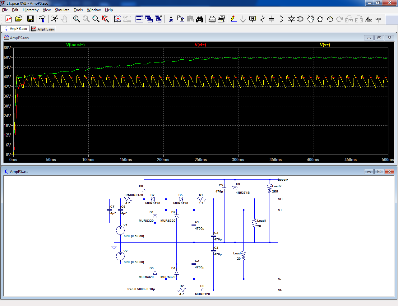
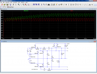
Then, you can reference the booster to the +rail:The regulator doesn't solve the higher voltage I would need for this design, which is +/-10v more for the low current stages.
Of course, it will follow it exactly, ripple included, but that's your choice.
Note that the booster is in fact a doubler, used as a capacitive supply and capable of providing a theoretical output of 3 x V+, in case you need it.
Using a shunt regulator (zener) limits the voltage (and therefore the losses) to what is required.
It is always preferable to "dissipate" reactive power in a capacitor rather than active power (heat) in a BD249 or BD250.
In addition, it is inherently short-circuit proof. C6 and C7 need to be 100V poly types of course.
There are many different ways to skin a cat, and the end result could be very pleasing, even if the method is ineffectiveAnd praised as this amp was at the time, I really do not think Luxman did not design it properly as you seem to imply.
I have nothing against doublers per se or any voltage multiplier, I use them quite a lot, and I have even rehabilitated them by dissipating some myths about their power factor, and I gave you examples loosely based on doubler topology, but I think that in this kind of application, they are generally dispensable: it is often possible to redesign the circuits, with bootstrapping or a better suited topology.If the problem are doublers instead of separate higher AC supply, not only Nelson Pass used it on his A75. Goldmund also did use doublers on their very expensive power amps, in spite of having separate AC secondaries.
In fact were those two applications which encouraged me to try it here, before the regulator.
Boosted rails (with doublers, or additional windings) are the easy solution for a number of problems, but if you do your homework, you generally end up with a leaner, meaner and more effective circuit, which not only does not need boosting but also has better general performances.
Anyway, before adding a regulator or boosted rails, you should seriously and objectively examine whether it is needed or not: what PSRR and voltage swing are you going to gain with the improvements?
There could be another problem to solve as a priority, and if you become obsessed with a single issue, you might miss it.
Attachments
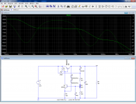
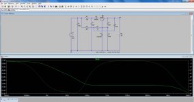
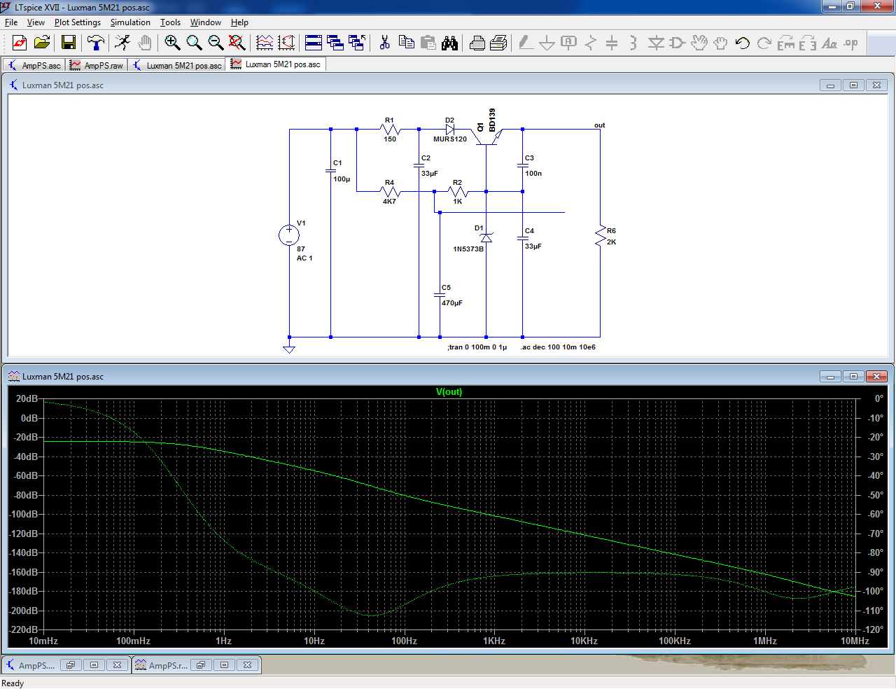
It is almost a plain-vanilla, transistor+zener regulator, except for two things:This is the original Luxman supply.
What do you think?
-one is rather ordinary: R1/C2 increase the rejection for higher frequencies
-the other is more unusual: C5 is returned to the output, rather than GND, probably to speed the startup, but it comes at a cost: the ultimate rejection is degraded and stays at ~80dB, instead of decreasing further:
It is a tradeoff due to the large time-constant, single pole filter, but the resulting regulator is reasonably effective, and certainly sufficient for the task.
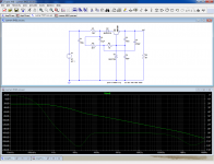
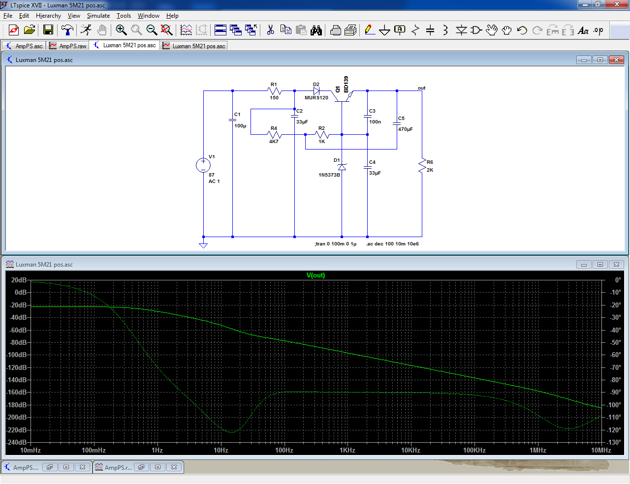
It is possible to get the best of both worlds by returning R4 downstream of R1 instead of upstream:
The multiple-transistor alternatives we discussed earlier have a much better static regulation, but for audio, that's unimportant, so it looks like a good alternative if you need it
Attachments
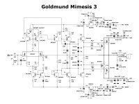
- it's a little strange DC supply voltage levels for me at that amplifier - what a reason to feed +-40V in "pre" cascades, and +-60V to output transistors? Doesn't it have to be vice verca?The regulator doesn't solve the higher voltage I would need for this design, which is +/-10v more for ....
- it's a little strange DC supply voltage levels for me at that amplifier - what a reason to feed +-40V in "pre" cascades, and +-60V to output transistors? Doesn't it have to be vice verca?
https://www.diyaudio.com/forums/att...lm317-voltages-goldmund_mimesis_schematic-jpg
I think you are mis-reading it. The "40V" is AC. Voltage-"doubler" rectifier makes this into 110V of DC. R29 may drop 20V. (But C9 is noted as 63V???) R28 R28 drops 5% so around 85V. (C5 may also be mis-specced?) In any case, the driver is probably running several volts higher than the power stage. Needed because the MOSFET gates need to be pulled-up several V, while Vds may go as low as 1V.
The doubler is fine. It is very-fine with cap makers. This uses a lot of large caps. However at today's prices for caps and (factory) assembly it is not extravagant. Regulation can be as good as any other scheme, with proper design. Regulation under load hardly matters here because the driver current is near constant. Note that this scheme does not regulate the *voltage*; it only has to be some higher than the main rails and *smooth*.
I am not being obsessive about anything about this project.
My purpose is to clone this power amp, and compare the results with the original one that my friend has.
Even I resist calling this project a clone, because none of the active parts will be the same as the original, my task is to try the same architecture Luxman used and listen to the results, comparing it with the original power amp. And see what I got.
Those circuits you enclosing would be a sim for the main supply and the doubler? What would the booster be for?
https://www.diyaudio.com/forums/att...lm317-voltages-goldmund_mimesis_schematic-jpg
I think you are mis-reading it. The "40V" is AC. Voltage-"doubler" rectifier makes this into 110V of DC. R29 may drop 20V. (But C9 is noted as 63V???) R28 R28 drops 5% so around 85V. (C5 may also be mis-specced?) In any case, the driver is probably running several volts higher than the power stage. Needed because the MOSFET gates need to be pulled-up several V, while Vds may go as low as 1V.
The doubler is fine. It is very-fine with cap makers. This uses a lot of large caps. However at today's prices for caps and (factory) assembly it is not extravagant. Regulation can be as good as any other scheme, with proper design. Regulation under load hardly matters here because the driver current is near constant. Note that this scheme does not regulate the *voltage*; it only has to be some higher than the main rails and *smooth*.
If you have separate secondaries you don't necessarily need a regulator, which is the case with the Goldmund.
It is almost a plain-vanilla, transistor+zener regulator, except for two things:
-one is rather ordinary: R1/C2 increase the rejection for higher frequencies
-the other is more unusual: C5 is returned to the output, rather than GND, probably to speed the startup, but it comes at a cost: the ultimate rejection is degraded and stays at ~80dB, instead of decreasing further:
It is a tradeoff due to the large time-constant, single pole filter, but the resulting regulator is reasonably effective, and certainly sufficient for the task.
It is possible to get the best of both worlds by returning R4 downstream of R1 instead of upstream:
The multiple-transistor alternatives we discussed earlier have a much better static regulation, but for audio, that's unimportant, so it looks like a good alternative if you need it
Nice suggestions.
I was just playing with the value of C4, increasing it, and the improvement seems to be interesting. Isn't it? Anything against that change?
The 3-transistor regulator seems to be the best still.
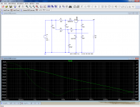
C4 is shunted by the zener, and to make a difference at low frequencies, it would need to be very large.
A cap is required, to shunt possible HF noise and keep the HF impedance low, but a modest value like 33µF is OK.
If you want to increase something, C2 is a better target: it will directly translate into PSRR, provided you use the alternate R4 connection.
BTW, another reason for the unusual C5 connection is probably to allow a lower working voltage
Yes, always using the alternate R4 connection. That was a good suggestion that could even be applied on the original Luxman.
Going from 33uF to 470uF on C4 lowers the results @ 10Hz from 70dB to 91dB.
But to get that we have to increase C2 to 1000uF. Though that means using a 100v cap for C2, that wouldn't be too small in size. Increasing that cap value would mean larger size and diminishing results.
Are there any values we could change in the three transistor regulator to improve results? As it is now we get 77dB @ 10Hz
Last edited:
- Home
- Amplifiers
- Power Supplies
- Using the LM317 with higher voltages