Just out of interest why you need such good power supply rejection ratios? Do you have something which is very critical. If you wanted a better result without the first stage and that big 2200uF cap you will need more voltage gain and more negative feedback. Probably a floating op-amp driving the pass transistor/mosfet. There's also http://www.ti.com/lit/ds/symlink/tl783.pdf.
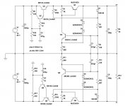
However what you have is just fine, I would add a current limit just in case you short the output and maybe a base resistor on Q3 so if the output is shorted the 2200uF won't dump the current into the base. You could replace Q3 with a darlington and then you won't need such a big cap.
However what you have is just fine, I would add a current limit just in case you short the output and maybe a base resistor on Q3 so if the output is shorted the 2200uF won't dump the current into the base. You could replace Q3 with a darlington and then you won't need such a big cap.
Last edited:
Well, maybe just because it was possible?
Hopefully those supplies will help others too.
Would you add those suggestions you made on the asc file? Perhaps I miss something if I put them.
Did just try using a Darlington for Q3, and it allows me to cut the base cap to 1000uF or 470uF, which is an excellent thing.
In fact I could just use 1000uF at the input, before the CM, and things would be fine too.
The Darlington models I have are very limited to get an accurate sim, just two TIPs. Though I also try two transistors in Darlington there, with similar PSRR results to the TIP. But I don't this Darlington choice would be critical for this application.
Interestingly enough, the negative PSRR curve is a bit worst than the positive one, but I guess that's the sim.
Elvee did suggest a protection transistor which I decided not to use, as specs worstened a "bit". The original supply didn't have any protection, so why worry?
Attachments
To improve on these CMRR results, on my simulations, only with the DeNoisator, NoNoiser and Jung-Didden regulators.
But I can't use any of them at these high voltages.
Recently a higher voltage IC was mentioned at the Superregulator thread: the OPA445.
I did mention that chip once to Jan Didden, a few years ago, to see if it could be an option for a higher voltage, low current superregulator, and he had said it was fine. But I couldn't remember the name now.
In any case, I think these much simpler regulators I got incredible help to get to are very good too. Less expensive too.
Some people, like Elvee, commented that he was no fan or didn't agree with regulating previous stages on an amplifiers.
But I do remember quite well the article on The Audio Amateur magazine about adding pre-regulation to an amplifier, and what were the reasons to do it: distortion and how minimum changes in voltage lines did affect the main current setting voltages. All that was measured with good instruments before and after the modification. The improved results were there to see. And for me the reasons were quite clear.
Erno Borbely and several other designers started to add higher voltage/low current stages to their power amps on the articles published on the magazine.
My simulation results showed great figures in PSRR and noise. The numbers for impedance went from 567milliohms @10hz to 75 milliohms @ 20KHz. Numbers at higher frequencies were even smaller and smaller. They can't compared to low voltage superregulators, that get to nanoohms or even picoohms at some frequencies. But power amplifiers deal with higher levels signals, so the "sacrifice" is not that important.
I can publish these curves if anyone is interested.
Most people get easily ineffective in their designs by ignoring some parts of a project enhancing other parts to unreal performance.
For lower noise and better tracking over a large frequency range a single regulator and virtual ground is better, a lot better.
@Elvee pointed out that a voltage multiplier can solve many problems with large Vin-Vout drop regulators.
In my opinion the best solution for low currents and high voltage is:
1.single transformer secondary wiring , a voltage multiplier 2...4x that will also reduce a lot of ripple compared to a simple rectifier bridge and filter attached to the right high ac voltage.
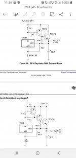
2.TL783 .It wasn't mentioned enough on this site.It's brilliant.
3. Virtual ground to split the supply after the regulation.
If higher currents are needed, voltage multipliers can be kept to a minimum number of stages or chucked and power transistors added.
I would not recommend any denoisator, nonoiser...added for the simple fact that you don't need that level of performance.I fully appreciate @Elvee's genious and expertise, but I wouldn't build one of those denoisators in a thousand years just because I don't see the point having that kind of complication and performance in any audio circuit ever built on Earth.
If you insist regulating the power amps too...you can do the whole amp plus preamp with two TL873 in series, one having a current booster for the power amp, each regulator having its own virtual ground refferenced to reg's output/2.
I wouldn't see the point in regulating power amps though...Check qsc usa1300 manuals for how to make a virtual power ground with no regulation that works for really high powers.There's a reason for qsc getting no1 in the stage amp industry...They know what high power is and how you get it for cheap.
The low power section for a preamp can use a simple resistor divider or any other active versions.
P.S.
I first used TL783 to regulate the 245 v dc line of a tube phono preamp with 2x 12ax7 and 2x 12at7 and 2x 12au7 in 2011.Dead quiet .I could hear the turntable motor when the tonearm was lifted and the whole 6 tubes preamp plus regulator was placed inside the turntable with no shielding on the same pcb where a power transformer also existed to match the 100v japanese motor inside the Onkyo turntable with the 220v...230v ac mains line.
TL783 is that good!
For lower noise and better tracking over a large frequency range a single regulator and virtual ground is better, a lot better.
@Elvee pointed out that a voltage multiplier can solve many problems with large Vin-Vout drop regulators.
In my opinion the best solution for low currents and high voltage is:
1.single transformer secondary wiring , a voltage multiplier 2...4x that will also reduce a lot of ripple compared to a simple rectifier bridge and filter attached to the right high ac voltage.
2.TL783 .It wasn't mentioned enough on this site.It's brilliant.
3. Virtual ground to split the supply after the regulation.
If higher currents are needed, voltage multipliers can be kept to a minimum number of stages or chucked and power transistors added.
I would not recommend any denoisator, nonoiser...added for the simple fact that you don't need that level of performance.I fully appreciate @Elvee's genious and expertise, but I wouldn't build one of those denoisators in a thousand years just because I don't see the point having that kind of complication and performance in any audio circuit ever built on Earth.
If you insist regulating the power amps too...you can do the whole amp plus preamp with two TL873 in series, one having a current booster for the power amp, each regulator having its own virtual ground refferenced to reg's output/2.
I wouldn't see the point in regulating power amps though...Check qsc usa1300 manuals for how to make a virtual power ground with no regulation that works for really high powers.There's a reason for qsc getting no1 in the stage amp industry...They know what high power is and how you get it for cheap.
The low power section for a preamp can use a simple resistor divider or any other active versions.
P.S.
I first used TL783 to regulate the 245 v dc line of a tube phono preamp with 2x 12ax7 and 2x 12at7 and 2x 12au7 in 2011.Dead quiet .I could hear the turntable motor when the tonearm was lifted and the whole 6 tubes preamp plus regulator was placed inside the turntable with no shielding on the same pcb where a power transformer also existed to match the 100v japanese motor inside the Onkyo turntable with the 220v...230v ac mains line.
TL783 is that good!
Attachments
Last edited:
I agree, some 10+ years ago I was using several different battery PSU's. Using it with the charger connected or no did not make any difference the important bit was to use the "ground" from the middle of the battery bank. Even relatively poor amplifiers improved by a large margin, and with any half decent amps there simply was no noise whatsoever regardless of how close I put my ear to the Radian 475 compression driver.a single regulator and virtual ground is better, a lot better.
Later tried virtual ground with some headphone amps and the effect was very similar.
Low current stages in an amplifier usually have current sources so there's no need for voltage regulation.In phono preamps you get the beneffit of lower noise supplies if the circuits psrr isn't great.I just believe in regulating low current stages in a power amp.
@KaffiMann virtual ground circuits with single regulators aren't talked about enough in the diy world...Usually the positive regulator is faster and overall better than the negative one.It's easy to see how difficult was to tame lm337 in a denoisator version in Elvee's thread.So chuck it...
Unlike many people here i have no theoretical background in electronics and low skilled theoretical people are used to repeat themselves and bragg about their " success history":
Most of what I learned was from schematics of real equipment, a lot of trial and error in several engineering jobs I could hardly get cause I didn't qualified for any of them from a theoretical point of view, some pondering, some books, a lot of randomized internet searches and some simulations that made me very lazy...but I think I was lucky to stumble upon some very high end equipment early in my hobby days and one such encounter was to have a Nakamichi cassette deck.That made me search all Nakamichi schematics and one of the most famous is BX300 which I think is the pinnacle of low noise preamp design.Of course it had a virtual ground even if it used a symmetrical low noise regulator.I recommend anyone who's low skilled in theoretical knowledge for maybe the 10th time to study that cassette player or any Nakamichi design for that matter.
- Home
- Amplifiers
- Power Supplies
- Using the LM317 with higher voltages