To build a large cap bank for speaker amp I opted to use many smaller caps, naturally the smaller caps are short and take up more flat area than the large value caps.
Im not using a PCB but hand wiring the caps with solid core wire, so there is some freedom when it comes to how the caps are wired into the system.
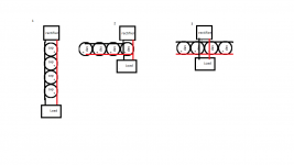
To highlight some of the possibilities :

In practice there would be a 10 caps, with pairs wired in series for postive and negative rails, so a 5x2 block of caps (plus the same for the other channel). Schottkys and a toroid are used which seems important to note here.
So does option 2 or 3, which is just a better version of 2, make the most sense? Essentially the rectifier and load are connected as close as possible and supply caps branch out from this point
Vs option 1, connecting the rectifier at one end of the cap bank and the load at the other, and have power run along the wiring for the caps...
Or does none of this really matter?
Also related Im wondering if I should add 2 rectifiers to trafo secondary, one for each channel, as currently a single rectifier will feed into each seperate 5x2 bank of caps on each channel, wouldnt be expensive and would bring it only one step away from being a monoblock
Im not using a PCB but hand wiring the caps with solid core wire, so there is some freedom when it comes to how the caps are wired into the system.
To highlight some of the possibilities :
In practice there would be a 10 caps, with pairs wired in series for postive and negative rails, so a 5x2 block of caps (plus the same for the other channel). Schottkys and a toroid are used which seems important to note here.
So does option 2 or 3, which is just a better version of 2, make the most sense? Essentially the rectifier and load are connected as close as possible and supply caps branch out from this point
Vs option 1, connecting the rectifier at one end of the cap bank and the load at the other, and have power run along the wiring for the caps...
Or does none of this really matter?
Also related Im wondering if I should add 2 rectifiers to trafo secondary, one for each channel, as currently a single rectifier will feed into each seperate 5x2 bank of caps on each channel, wouldnt be expensive and would bring it only one step away from being a monoblock
Attachments
Last edited:
Fundamentally you want to keep cap charging pulse away from the currents sourced by the amplifier. this is obviously not possible to ensure in ideal terms, the design needs to pay attention to the fact that both currents will usually flow along the same wire.
This means 1 is the only possible approach of the three you've listed. The best way is to separate paths for each cap, but that is a *lot* of wire, and it needs to terminate somewhere.
This means 1 is the only possible approach of the three you've listed. The best way is to separate paths for each cap, but that is a *lot* of wire, and it needs to terminate somewhere.
Option 1 will give least hum. Option 3 will give lowest output impedance. The difference will be small.
If you are using one set of rectifiers to feed two sets of caps then you have to be careful to avoid introducing an interchannel ground loop at about the worst possible place - right in the middle of the PSU. You either need one PSU feeding two channels, or two PSUs (ideally with separate secondaries) each feeding one channel. You cannot have two things both separated and connected!
If you are using one set of rectifiers to feed two sets of caps then you have to be careful to avoid introducing an interchannel ground loop at about the worst possible place - right in the middle of the PSU. You either need one PSU feeding two channels, or two PSUs (ideally with separate secondaries) each feeding one channel. You cannot have two things both separated and connected!
Option 1 will give least hum. Option 3 will give lowest output impedance. The difference will be small.
If you are using one set of rectifiers to feed two sets of caps then you have to be careful to avoid introducing an interchannel ground loop at about the worst possible place - right in the middle of the PSU. You either need one PSU feeding two channels, or two PSUs (ideally with separate secondaries) each feeding one channel. You cannot have two things both separated and connected!
The primary aim is to improve quality of bass transients by adding more caps, right now the bass ''sags'' during any heavy bass.
It seems like the best topology for ideal power delivery would be wiring each cap individually to keep impedance to the load as low as possible for every cap as suggested by sangram (though I couldnt imagine any practical way of doing without having to use longer wire for some of the caps... you would need have the caps in a radial ''flower'' formation).
In any of the above options some of caps will always face more impedance than others, what exactly would the slightly lower output impedance of option 2 mean for the circuit? it would be more related to HF performance?
Avoiding ground loops is tricky to comprehend when it comes to P2P wiring.
The only place each channels ground would meet in the amp is at the trafo centre tap, so I picture the ground wiring paths forming a ''V'', there is no ''loop'' in the literal sense.
If the ground from the source is connected at this same point its seems a ''loop'' is still avoided, you just have a ''Y'' but I guess you would only create other grounding issues with this... that is assuming this scenario isnt actually creating a ground loop to begin with.
It is highly likely that the source (or preamp etc.) will join the left and right grounds, so you have to be careful how you join them in the power amp PSU because this has the largest circulating currents. A ground loop is almost unavoidable, so the aim is to avoid injecting ripple into it. The secondary centre tap is a bad place to join the grounds, so the best option is either one PSU ground bus (with the audio circuit grounds connected to it at the 'clean' end) or two completely separate PSUs (meaning two secondaries). DIYaudio is full of attempts to get round this problem.
If you are getting significant sagging on loud notes then you need a bigger transformer, not different reservoir bank wiring.
If you are getting significant sagging on loud notes then you need a bigger transformer, not different reservoir bank wiring.
thanks for the advice, would have wasted a lot of time wiring every up the wrong way.
currently there is 8000uf for the positive and negative rails with a 250VA transformer, The sagging is not significant but im looking for best possible performance, bass quality is truly excellent at lower volumes and I want to maintain that into moderate volumes, where it starts to become only ''pretty good''. I felt the weakest link was the reservoir caps, 10000uf is commonly mentioned as a minimum with some using many times that.
btw I didnt mean the wiring would have any audible affect on the bass saging, only adding more capacitance would, I was just curious if what I described would be optimal way of wiring for this problem in theory. Also what the effect of lower output impedance of option 2 would be in theory.
Last edited:
I'd add use thicker wire on the rectifier side of the caps, they have significant current pulses and will drop more volts across the wiring if its all identical. The wires to the load can be thinner.
There's no point making the wire resistance much lower than the ESR of the capacitor bank though, you'll get diminishing returns.
Note that any runs of wiring between sections should be twisted otherwise you'll have large loops carrying heavy currents which will induce hum into nearby circuits. This usually means all three wires twisted, unless separate secondaries and rectifiers are used per rail.
Finished adding the caps and it did help a lot with the bass thankfully, though i feel like overall sound quality kind of suffered in some ways. I wondered if its that improving the bass response of the amp could cause MF and HF performance of the full range speakers to suffer.
Either it's me or caps ''breaking in'' (20 x 2200uf Panasonic FR) but
its sounding a lot better after using for a while.
It's the break-in of the capacitors.
Last edited:
I do not understand ecap break in. If it is so, what is the mechanism and why
would the manufacture not identify this phenomenon in the data sheets?
Read the mfr data sheets carefully, especially regarding storage, shelf life, testing, etc.
These things will be discussed.
Once the parts are made, they sit in mfr inventory, then in distributor inventory,
then in end user inventory, then inside the finished product in inventory.
This could be a year (or even several) of degradation due to non-operation.
- Status
- This old topic is closed. If you want to reopen this topic, contact a moderator using the "Report Post" button.
- Home
- Amplifiers
- Power Supplies
- Hand wiring approaches for cap banks