Hi All,
First post here,
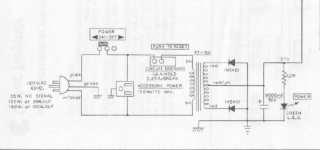
I'm rebuilding an old 100w s.s. Raymer pa amplifier. Broken down the chassis and built back up with new parts and turret boards - hardwired. Been a great experience so far! I'm checking the circuit for shorts and have a question about this rectifier scheme attached below.
Searched all over and have never seen this type of reverse/negative layout for the diodes in a power supply.
Anyone here recognize this or could explain why they chose to use it?
Center tap is 0V - this looks like there's current passing from capacitor to signal ground from the neg side of the capacitor going to the diodes.
So, how is current flowing through this power supply and why are the diodes being used in reverse?
First post here,
I'm rebuilding an old 100w s.s. Raymer pa amplifier. Broken down the chassis and built back up with new parts and turret boards - hardwired. Been a great experience so far! I'm checking the circuit for shorts and have a question about this rectifier scheme attached below.
Searched all over and have never seen this type of reverse/negative layout for the diodes in a power supply.
Anyone here recognize this or could explain why they chose to use it?
Center tap is 0V - this looks like there's current passing from capacitor to signal ground from the neg side of the capacitor going to the diodes.
So, how is current flowing through this power supply and why are the diodes being used in reverse?
Attachments
Last edited:
It's a full wave rectifier with a center tap. It doesn't matter if You are cutting positive or negative peaks. What matters is the correct polarity connection after it.
Perhaps the author wanted to emphasize that the ground is indeed negative...PCB routing facility perhaps ?
Perhaps the author wanted to emphasize that the ground is indeed negative...PCB routing facility perhaps ?
If you reverse the direction of the diodes and connect the center tap of the transformer to ground and the cathodes of the diodes to the + terminal of the capacitors you have the common way of doing the same thing. It makes no difference. The only advantage to this layout is that if you had a high power supply with stud mounted rectifiers that had their anode connected to the case you could mount the rectifiers to a grounded heat sink with no insulators. The 1N5401 are not stud mounted so it makes no difference.
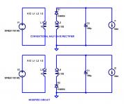
It's a "full wave rectifier" composed of two "half wave rectifiers" operating on opposite phases, thanks to the two secondary windings.
Each of the half wave rectifiers is a tiny modification of the traditional, well-recognized circuit. Just slide the diode from one end of the winding, to the other.
_
Each of the half wave rectifiers is a tiny modification of the traditional, well-recognized circuit. Just slide the diode from one end of the winding, to the other.
_
Attachments
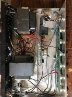
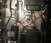
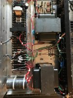
Thank you all for the insight, nothing beats experience!

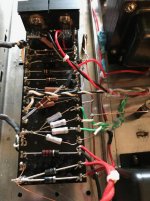
Few pics below before and after-
That's what they did, straight to chassis for the whole ground plain. Brutally effective and solid build for a PA amp. Must have had a 150W gun to stick those (welds) to the chassisThe only advantage to this layout is that if you had a high power supply with stud mounted rectifiers that had their anode connected to the case you could mount the rectifiers to a grounded heat sink with no insulators. The 1N5401 are not stud mounted so it makes no difference.
MJ- So are you suggesting per the diagram that i could reverse only D1?Each of the half wave rectifiers is a tiny modification of the traditional, well-recognized circuit. Just slide the diode from one end of the winding, to the other.
Few pics below before and after-
Attachments
Hi MJ,It's a "full wave rectifier" composed of two "half wave rectifiers" operating on opposite phases, thanks to the two secondary windings.
Each of the half wave rectifiers is a tiny modification of the traditional, well-recognized circuit. Just slide the diode from one end of the winding, to the other.
_
I see what you mean, your diagram shows both ways, got it. Thank you!
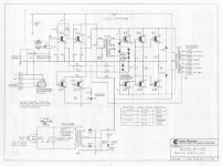
full schematic:
Attachments
Why do you want to modify it, if it is OK?
A few reasons,
1) I'm learning and this is a simple circuit to work on
2) The amp was free with nice trannies
3) It didn't sound great, the caps were shot, tubby bass, etc. But when i bypassed the front panel (mostly tone and mixing), and added new caps on the inputs and power supply, it sounded much better. It's a nice, punchy mono amp, worth seeing what it can do with a proper signal ground and new components.
I did this to learn on the cheap as it was a doner. Currently tracking down a short, so revisiting the circuit path starting with power supply and transformers. No luck yet, the needle is still in the haystack!
You would need to move both diodes, but nothing needs 'reversing'. The diode still has to face the same way with respect to the ground and the reservoir capacitor, otherwise you get a polarity inversion and the capacitor explodes. I cannot see the point of making this change.BillBr said:MJ- So are you suggesting per the diagram that i could reverse only D1?
...how is current flowing through this power supply and why are the diodes being used in reverse?
As said: it works same as any 2-diode rectifier.
I must admit I have not seen that exact "reverse" connection. But it does the right thing, which is all that counts.
More often we see Common Cathode, *especially* in tube rectifiers, because tube cathodes are costly but more economical made 2-in-1. (Also filament/heater power!). But Common Anode works just as good.
You'd think solid-state diodes would not care. But there is history. Long ago if you needed BIG low-voltage rectifier you got an Alternator Diode. And these had to bolt to a heatsink (or alternator frame), preferably without annoying insulators. While they were made both common-anode and common-cathode, maybe Raymer came across a crate of common-anode diodes at close-out price. You don't have bolt-in diodes. Maybe the fat epoxy pack came later, or Raymer used them in the smaller amps, but kept the same wiring scheme.
Attachments
It will be interesting to see if hum is noticeable or objectionable, what level of global feedback is applied, and how well balanced the idle current will be in the output transformer.
Those are great points, i'm interested to know too. The output transistors aren't perfectly matched, but theyre straight from ONsemi same codes.
The idle current is actually what i'm watching because with the new parts- and the vintage AB's.
One way this was built intrigued me. They used a darlington transistor with the C-B jumpered instead of a couple diodes for the driver regulation. They bolted the darlington to the chassis, ran a line to the emitter, and it stays at 1.1V all day.
Feedback off Q1 goes to 8ohm tap yes but i don't have any readings yet. Will post some up when it makes sound.
Thanks for the insight and for the drawing. Makes perfect sense now. They did use similar circuits and yes used common parts for sure. I had to dig up a good bit of info on their amps before working on it.
I just thought, there's no reason for this not to sound good, all the specs are straightforward, and i can learn along the way.
I just thought, there's no reason for this not to sound good, all the specs are straightforward, and i can learn along the way.
This was made in 1984? How interesting. Must have been the most conservative amp manufacturer ever. Typical valve topology with a phase splitter, cap coupled front end, full wave rectifier and "valve type" nfb and yet an ultramodern led ")
Looks like a design put in production in the early 60s and very cautiously revised later on. Why change a good thing?
What is the bandwidth? 50Hz-12kHz?
Looks like a design put in production in the early 60s and very cautiously revised later on. Why change a good thing?
What is the bandwidth? 50Hz-12kHz?
> most conservative amp manufacturer ever.
Rauland-Borg in the 1980s (even mid-1990s) was even more conservative. (Also better-built, thus likely higher price.) Very early-1960s designs. Worked fine, good specs for the app, despite being more industrial/shaker market than Music Hall.
R-B is still in business and coming up on 100 years. Fabulous success for an audio company.
Yea I think you're right. They produced tube amplifiers in the 60's though I haven't seen schematics from that era.This was made in 1984? How interesting. Must have been the most conservative amp manufacturer ever. Typical valve topology with a phase splitter, cap coupled front end, full wave rectifier and "valve type" nfb and yet an ultramodern led
Looks like a design put in production in the early 60s and very cautiously revised later on. Why change a good thing?
What is the bandwidth? 50Hz-12kHz?
Bandwidth wasn't published on the data sheets i found and the transformers aren't really marked in any way to find out more. But the amp is very nice on bass and would guess that it may go up to 15khz or more. The components would achieve good performance in pretty much any audio circuit. 2N3055 output transistors are a something of a classic I learned, starting with RCA or Fairchild in the early 60
's iirc. But it sounds much better than i ever expected it to with my JBL Horizons.
> most conservative amp manufacturer ever.
Rauland-Borg in the 1980s (even mid-1990s) was even more conservative. (Also better-built, thus likely higher price.) Very early-1960s designs. Worked fine, good specs for the app, despite being more industrial/shaker market than Music Hall.
R-B is still in business and coming up on 100 years. Fabulous success for an audio company.
Fascinating history, didn't know they existed until now. Thanks for the link
- Status
- This old topic is closed. If you want to reopen this topic, contact a moderator using the "Report Post" button.
- Home
- Amplifiers
- Power Supplies
- Rectifier Diodes Reversed