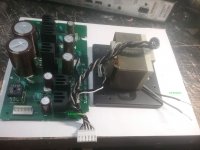
I salvaged this transformer and power supply from a Denon DVD player. Tonight I attached an electrical cord and plugged the transformer in and did not get any reading with my meter on the AC setting. As far as I can tell the grey and black wires in the photo are the primary and the 6 back and grey twisted wires are the secondary.
The transformer ID number is written on the top: D00 233 645 5701 1 with another number: GT 552 TK (Y) written below it. I spent 20 minutes scouring the NET for information on this transformer but no luck. Anyone know of a resource I missed for transformer I.D.?
Also am I correct in my assumptions about the input/output?
Thanks for any info.
Tony
Attachments
Last edited:
Hi Tony,
I have salvaged a lot of transformers and even found some where I do not know the origin. I have a simple method I use to analyze a transformer:
I use my Ohm-meter for a start and try all combinations of wires to find out which wires are connected to which. The wire(s) with the highest DC impedance is normally the primary. "Normally" because if you recover the transformer from a particular use like the power transformer in a micro-wave, it has a higher secondary voltage than primary voltage. There may be more primary wires if it is meant for different input voltages. The primary windings are normally grouped together.
Then, I draw a small sketch of how the wires are connected to one another through the windings. If there is no DC impedance, you will have no useful output voltage (only a noise voltage without power).
Then the voltage test. I connect a 1A fuse in series with the primary and connect the primary side to the net (WATCH OUT FOR THE HIGH VOLTAGE ON THE PRIMARY SIDE! DANGER!).
I know from my sketch from which secondary wires I can expect an AC voltage. No DC connection - no AC voltage. DC connection and a good primary connection and you will have an AC voltage of some kind on the secondary, unless the wires are connected by a regular short-circuit. The voltages I measure I can add to my sketch.
The power capacity I estimate from the size and eventually information on the apparatus I got it from about maximum power consumption of the apparatus.
Your photo does not well show the wires coming out of the transformer.
Last edited:
Thanks for the replies. I have downloaded the service manual / schematic and it is not much help as the transformer/power supply have no identifying/spec. information. But I now know that the transformer outputs 15 volts-AC on one set of the secondaries. My confusion about the output measurement in my original post was because I made the measurements with my meter set on volts-DC...it was late and I am prone to dumb-assery when I am tired.
I now know that the power supply outputs 18 volts-DC but I need 15 volts-DC for my project and there are no trim pots to adjust the output voltage...any ideas on how I can reduce the output to 15 volts?
Tony
I now know that the power supply outputs 18 volts-DC but I need 15 volts-DC for my project and there are no trim pots to adjust the output voltage...any ideas on how I can reduce the output to 15 volts?
Tony
Last edited:
It all depends on how much current you are going to use. If it is below 1A you can use a regular chip, say a 12V regulator and add a resistor between the output and IC common terminal, and another resistor from the IC common terminal to circuit ground. To increase the voltage linearly, use a linear pot connected in series with the second resistor that connects to circuit ground. You will have to allow several milliamperes to pass to allow for the regulator's internal current flactuations.
Let us say, you are going to allow 10mA to flow through the resistance chain.
With 12V, the resistance between the regulator's output and regulator's common will be:
V = IR => Ra = 12/10e-3 = 1.2kOhm
Since you need 15V, allow 2V across the other resistor:
Hence, Rb = 2/10e-3 = 200 Ohms.
And allow another 2V across the preset:
A 220 Ohm linear preset should allow you to adjust the voltage from 14V to 16V.
Post Scriptum:
The current rating of a 1A voltage regulator, can be increased by using a power transistor whose maximum base current rating is higher or equal to the chip's maximum output current. In this arrangement, the power transistor's base is connected to the chip's output, the collector to the positive terminal of the power supply, and the emitter becomes the new enhanced output. To allow for Vbe, use a diode in series with the resistor chain with one end connected to circuit ground.
N.B: Power transistors require a heatsink even for testing purposes.
Assumptions: The chip is assumed to have a negative common and positive output. With this arrangement, the power transistor has to be NPN.
Last edited:
Thanks for the replies. I have downloaded the service manual / schematic and it is not much help as the transformer/power supply have no identifying/spec. information. But I now know that the transformer outputs 15 volts-AC on one set of the secondaries. My confusion about the output measurement in my original post was because I made the measurements with my meter set on volts-DC...it was late and I am prone to dumb-assery when I am tired.
I now know that the power supply outputs 18 volts-DC but I need 15 volts-DC for my project and there are no trim pots to adjust the output voltage...any ideas on how I can reduce the output to 15 volts?
Tony
There are some heatsinks with transistors or voltage regulators. If you tell us the types, perhaps we can adapt the circuit. It seems rather simple.
There are some heatsinks with transistors or voltage regulators. If you tell us the types, perhaps we can adapt the circuit. It seems rather simple.
Thanks for all the replies guys. I have identified the regulators on the board an indicated them in the image attached. I am a rank amateur when it comes to this sort of thing so any and all help is appreciated.
Attachments
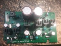
Thanks for all the replies guys. I have identified the regulators on the board an indicated them in the image attached. I am a rank amateur when it comes to this sort of thing so any and all help is appreciated.
Hi Tony,
Thanks for checking. Could you please list the type numbers from left to right in plain text? I have major problems reading the small red numbers on the photo.
Hi Tony,
Thanks for checking. Could you please list the type numbers from left to right in plain text? I have major problems reading the small red numbers on the photo.
From left to right: 7805A, 7905P, 7912P, 7812A, 7808A, 7805A
My use of the power supply is for a headphone amp kit, I lost the factory power supply but I do have a photo that dictates "15 volts at 150ma". I don't know what precision is required or what will happen if I apply 17 volts to the boards.
Thanks for all the help.
Thanks for all the help.
Attachments
Hi Tony,
The 150mA is fine.
I had no knowledge of the use other than "your project". It seems to be for a nice headphone amp. Then it deserves a decent solution and not just a "quick and dirty" adaption.
Be aware if the headphone amplifier actually needs only +15V (a single voltage) or +/-15V (a dual symmetrical voltage). In both cases, your transformer and most likely also the DENON board can be used.
You have 15Vac on your transformer which is fine. You have a 7912P and a 7812A voltage regulator on your DENON board. You just need to replace them with a 7915 and a 7815 respectively. Then you should have +/- 15V on your board. If you only need a single 15V voltage, you only need to replace the 7812A into a 7815.
7915 and 7815 are trivial components that can be bought cheap in any electronic shop.
> Using the -5V and the +8V outputs would give us 13V voltage.
It is likely some of these regulated outputs are common-ground and can not be aribtrarily put in series.
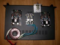
My interpretation is in the picture. +/-5V for DAC, +/-12V for opamps, and both +5V and +8V for CPU or lamps?
> a photo that dictates "15 volts at 150ma".
The photo suggests + and - 15 Volt supply.
98% of +/-15V gear will work fine on +/-12V, just a minor loss of headroom.
It is likely some of these regulated outputs are common-ground and can not be aribtrarily put in series.
My interpretation is in the picture. +/-5V for DAC, +/-12V for opamps, and both +5V and +8V for CPU or lamps?
> a photo that dictates "15 volts at 150ma".
The photo suggests + and - 15 Volt supply.
98% of +/-15V gear will work fine on +/-12V, just a minor loss of headroom.
Attachments
> Using the -5V and the +8V outputs would give us 13V voltage.
It is likely some of these regulated outputs are common-ground and can not be aribtrarily put in series.
My interpretation is in the picture. +/-5V for DAC, +/-12V for opamps, and both +5V and +8V for CPU or lamps?
> a photo that dictates "15 volts at 150ma".
The photo suggests + and - 15 Volt supply.
98% of +/-15V gear will work fine on +/-12V, just a minor loss of headroom.
Right you are.
If the +8V output and the -5V output have common ground, it should leave us with 13V between the two outputs. The voltages are already "stacked" around the ground potential. But, it will only form a single voltage.
Your analysis of the previous use seems very right as well and +/-12V should do for the headphone amp.
Personally, for a permanent construction, I would tidy-up by removing all the regulator circuits I do not need and replace the +/-12V with +/-15V so all is "spot-on".
> replace the +/-12V with +/-15V so all is "spot-on".
IF the raw supply will cover the extra 3V. Some of these CD players were cut to the bone. Also a HARD-worked headphone amp sucks more current (lower raw supply) on loud peaks than a CD box's opamps will.
And my *personal* experience with high-voltage headphone amps and hearing loss suggests we "never" need +/-15V supplies to a headphone amp. Even my "loudness masterpiece" only swung 11V peaks.
> replace the +/-12V with +/-15V so all is "spot-on".
IF the raw supply will cover the extra 3V. Some of these CD players were cut to the bone. Also a HARD-worked headphone amp sucks more current (lower raw supply) on loud peaks than a CD box's opamps will.
And my *personal* experience with high-voltage headphone amps and hearing loss suggests we "never" need +/-15V supplies to a headphone amp. Even my "loudness masterpiece" only swung 11V peaks.
Your experience with headphone amps undoubtedly exceeds mine and +/-12V is most likely enough.
With that size of transformer (15W?), 15Vac at the secondary and the need for 150mA, I guess there are margins for even +/-15V. At 150mA, the drop-out voltage is rather 2V.
OP, you can choose between +/-12V, which is already available on the DENON board, or modify the board to +/-15V as mentioned in an earlier posting. Both should work fine and even with +/-12V you should have more than enough power for your headphones.
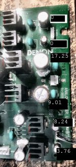
Thanks again for all the help. The photo attached is what I get when I measure the power supply, I have also attached the photo of PRR's interpretation for comparison.
I see that I have 3.76V and 8.24V on the far left 3 pin outlet which will make 12V but I don't know how to combine these (or other pins on the board) get the 12V out that I need.
I see that I have 3.76V and 8.24V on the far left 3 pin outlet which will make 12V but I don't know how to combine these (or other pins on the board) get the 12V out that I need.
Attachments

- Status
- This old topic is closed. If you want to reopen this topic, contact a moderator using the "Report Post" button.
- Home
- Amplifiers
- Power Supplies
- Transformer question.