Line frequency harmonic supression filters are quite common in power electronics for industrial use where lots of AC motors, inverters and welding and other power euipmenets are used. These usually supress the harmonic freunccy from 3rd to 20th harmonic and allows pure sine wave to the load. The fundamental frequency here is 50Hz and harmonic supression will be for 150Hz and above.
Are such kind of filters also relevant for use with audio gear? Actually i tried building one with CFL chokes and capacitors and found the tube amplifier power transformer pretty cold even after 2+ hours of use. Also the sound was free of any harshness and sparkle and the mids very very open and less listening fatigue. Would be glad to hear from experts here. I am not sure if this is how music should be as the extra sparkle from the music has just vanished for the better.
Are such kind of filters also relevant for use with audio gear? Actually i tried building one with CFL chokes and capacitors and found the tube amplifier power transformer pretty cold even after 2+ hours of use. Also the sound was free of any harshness and sparkle and the mids very very open and less listening fatigue. Would be glad to hear from experts here. I am not sure if this is how music should be as the extra sparkle from the music has just vanished for the better.
Last edited:
Apart from EMI compatibility, if the there is a problem with strong harmonics in an audio device, the problem would be that these somehow manage to enter the audio signal path, which reveals itself as hum or buzz. The power supply itself does not care too much about what the input wave looks like.
Last edited:
EMI filters are employed with switch mode power supplies to stop interference from the power supply entering the household supply and then the national grid/supply lines or whatever your country calls it.
The have no effect on the amplifiers ability to have improved sound!
A simple 100nF 250v class X capacitor across the supply to your valve amplifier is sufficient to remove any mains born noise.
The have no effect on the amplifiers ability to have improved sound!
A simple 100nF 250v class X capacitor across the supply to your valve amplifier is sufficient to remove any mains born noise.
Thanks TBTL, Jonsnell for your reply.
I am not referring to any EMI or RF noise that gets picked up in the supply line from the utility company to our home wall outlet but the harmonics of the fundamental 50Hz frequencies which are quite a bit till 11th or 19th harmonics. This would be less to do with the power supply of the amplifier as they do have large capacitors and small ones to filter the ripple. The harmonic filter mostly i think is helping the amplifier transformer as they are now not heating up as before - so implying low core and eddy current losses. Also i am getting quite a different sound with and without this filter. Without the filter, the transformer is warm in 15 mintues and quite hot in 45 minutes. Now they are barely warm with 2+ hours of use.
As most of us are tuned to listen to coloured sound, first listen with this harmonic filter will give a feeling of something is suck out of music with reduced sparkle, brillance and less energy. But after careful listening for 15+ minutes i am feeling much relaxed, enjoyable and pleasant. Even my wife and daughter noticed this and asked me why the setup is now very quite unlike before. Looking for answers.
Last edited:
Thought the harmonic suppresors are these kinda active filter that samples the harmonic frequence and inject the opposite wave via an IGBT into the powerline, but it seems Hari you are talking about a LC Filter on the powerline? IMO it is a very common product for the commercial HiFi market, can reduce harshness and brightness in the treble. But those products are mostly named power conditioner and cost lots of money.
Be care about the use of such filters. If they enters in resonance between them and the power trafo or any reflected capacitive or inductive suceptance from the secondary(ies), at the line frequency or their harmonics, unexpectedly high voltages or currents can flow in the circuit causing burning, explosion or fire.
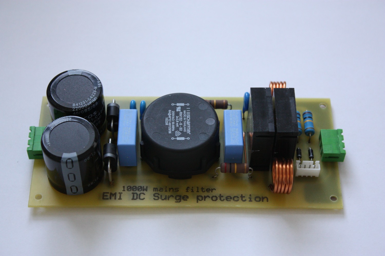
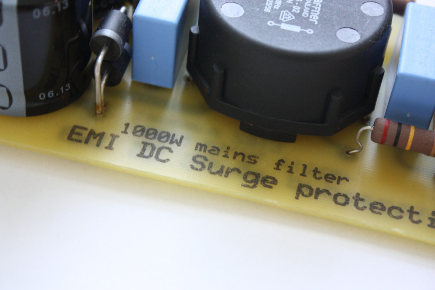
They are before the transformer on the primary side. May be i shall post a schematic and image tomorrow.Are your filters before or after the transformer? After the rectifiers?
Last edited:
Be care about the use of such filters. If they enters in resonance between them and the power trafo or any reflected capacitive or inductive suceptance from the secondary(ies), at the line frequency or their harmonics, unexpectedly high voltages or currents can flow in the circuit causing burning, explosion or fire.
Thanks for informing. This filter is in parallel to the transformer primary and offers high impedance for 50Hz and from 150Hz onwards a relatively low impedance for the harmonics. This needs to be switched on/off along with the amplifier for resonance to match exactly at 50Hz else they will fail. I have been using it for past one week and have not seen any component heating of the choke or the capacitors, though i have used them around 2 to 3 hrs on a daily basis past one week. I will keep a note and post again.
Hari,
Such line harmonic filters can be used industrially for many reasons.
If you are hoping that the filter will improve the voltage waveform seen by the amplifier then have you confirmed an improvement (by measuring mains AC voltage harmonic levels before and after application of filter), or are you just using your ear?
If mains voltage distortion is your concern, perhaps because you have measured what is available to the amplifier, then you need to appreciate that the distortion may include a lot of distortion forced on the mains AC by both nearby equipment, as well as your amplifier itself !
Similarly, if you apply a harmonic filter to your AC mains then it will become a low impedance path for harmonic currents that originate from anywhere nearby , as well as from your amplifier. That could mean substantial current levels coming in to your house/building/room, from industrial equipment nearby, and those current levels could exceed the trip levels of protection devices.
I would strongly recommend you do not add circuitry to the AC mains supply unless you have appropriate measurement equipment to know what it is experiencing, and have in place appropriate protection devices and have a professional awareness of what is and could be going on.
Thanks trobbins for your inputs. I have been using this for around one week and have two MCBs in the path which has not yet tripped. Also i have physically touched the inductor and capacitor and they run cool even after 2+ hours of usage which means there is no major power loss across them. But what you mentioned is also very logical. Perhaps connecting this to an 1:1 isolation transformer would be more safer. What do you think?
I can't see the connection between filtering harmonics and a cool transformer. Does the filter remove DC too?Hari said:Actually i tried building one with CFL chokes and capacitors and found the tube amplifier power transformer pretty cold even after 2+ hours of use.
Be aware that the main source of harmonics will be PSUs; yours and others on the same mains circuit.
I am building a mains filter now, and it is not only for EMI but also to remove any DC in mains to prevent power transformer from buzzing etc. I have already built this filter some years ago and now building another on. Just this time not on a DIY pcb, but traced with eaglePCB. Already got all the parts.

Not in english, but you can translate it i am sure") Audio schemos leopard
Audio schemos leopard
Will be used with 1kW isolation toroid also.
Not in english, but you can translate it i am sure
Audio schemos leopardWill be used with 1kW isolation toroid also.
There are active and passive harmonic filters, which operate very differently. You are asking about passive filters, so I will restrict this post to those for now.
Passive filters are not used to block (like say an EMI filter does). They are tuned in such a way to sink harmonic currents that are known to be problematic. These currents do NOT come from the supply, they are generated by the load. Filters are normally placed near the harmonic-generating load such that those known harmonic currents do not propagate up into the supply system; they are sunk by the filter. Technically, they provide a lower impedance than the supply system, so it is a current divider.
Without the filter, the harmonic current must pass through the entire supply system impedance, creating a harmonic voltage drop. This is what causes flat-topped sine waves on the voltage supply. The utility (near the point of generation) is a very clean harmonic-free sine wave. The further away from that generator you get the more harmonic voltage is created by the harmonic currents passing through it, and you see this at your electrical panel.
With regards to your power supply, it is a harmonic generator, it is part of the problem. If you were able to provide your amp with a perfect voltage free of harmonics, your amp will throw back at it a plethora of harmonic currents. This applies to capacitor input, choke input, and yes even switching supplies that are power factor corrected (though they are pretty darn good).
Your voltage supply, not having 0.0000000 ohms of Thevenin impedance, will therefore distort due to those harmonic currents the amp has generated.
Now, you come out and install a passive filter near the amp input. This might improve the voltage supply if you have carefully selected the resonant point of the filter to match the harmonic current(s) you know the amp is producing. By the nature of your question, you have not knowingly matched any filter performance, so you should not expect a voltage source improvement. In fact, what you could have done is caused a sink for harmonics generated else where in the home, which will drop voltage across your branch wiring and add additional harmonic voltage drop (distortion).
You should also be aware that a passive filter as a general rule will NOT improve the voltage waveform present at the panel; this is largely dictated by the utility and the bulk power grid. You are wanting to restore harmonic voltages that have dropped between the supply and point of use; you would not obtain this with passive filters. That would be the role of active filters. In short, you cannot expect a passive filter to clean up the voltage waveform; at best you can expect it to reduce the voltage distortion created by your amp, and that only. In relative terms, your amp adds very little distortion to what exists on the line.
There are, for some people that have the software tools and understanding of power system resonance, who can create voltage rise by overcorrecting at the point of use, utilizing passive filters to act as 'little generators', but this is not within scope of your application, not by a long shot. My suggestion is don't even try to pursue this. I do this on occasion, and it requires careful analysis of frequency response and damping to ensure the passive components are not overloaded. Metallized film is generally discouraged; oil filled film/foil preferred. UL/FM Global are starting to frown on oil filled capacitors, so those of us that have to try and design custom filters for industrials are running into compliance issues. Then there is the challenge of load variability - passive filters work well when the load is known and constant. Turn circuits on and off, and performance changes, sometimes unpredictably.
If you are willy-nilly installing LC filters hoping for improvement, I would suspect you are either accomplishing nothing or are resonating in bad ways with parallel loads, potentially overloading the filter components and adding distortion. Have you intentionally selected the R of your RLC filter (there is always R present) for proper Q? If not, I would say it is nonideal, and could cause problems.
Not to argue about it, but if you have no measurements (FFT) of with/without filter, then I would bet money you have effectively gotten lucky, and done nothing with the filter addition other than dropping some voltage. You have 117Vrms at the receptacle, feed into the filter, then have 115Vrms at the amplifier. That's all you have accomplished, which might cause your transformer to run a bit cooler. It isn't easy to develop strong resonance in real world residential power systems, so you have avoided the worst case scenario, but have not acquired the goal of 'cleaner' voltage.
If you have a sound card, a filament transformer and FFT software it would be easy to prove with/without performance.
Hari,
Maybe you are using a Ferroresonant power supply ( aka constant voltage transformer )
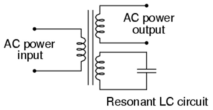
What is a Ferroresonant Power Supply? - Sunpower UK
Maybe you are using a Ferroresonant power supply ( aka constant voltage transformer )
What is a Ferroresonant Power Supply? - Sunpower UK
Thanks to everyone for their reply and letting me know about pitfalls with the implementation. What i have done now is added a series of common mode chokes on the line and neutral ( 3 of them in series) which is giving me an inductance of 40mH and a resistance of 0.1 ohms. i have added an interference supression Y capacitor 0.01uF at the input side and output side. No X capacitors between line and neutral. This will reduce any common mode noise and supress any RF and EMI i think.
Audio gear *generates* strong 3rd and 5th harmonic currents, due to the rectifier power supplies. If your incoming waveform were a little “flat topped” it won’t hurt anything - it will make life easier on your rectifiers by increasing the conduction angle and actually improving the power factor. If there is 3rd and 5the harmonic voltage present (which a flat topped sine will), there will be real power delivered in the 3rd and 5th harmonic currents drawn by the rectifier/capacitor load. The odds actually go up much higher, but most of the reactive power is accounted for in just the 3rd and 5th.
- Status
- This old topic is closed. If you want to reopen this topic, contact a moderator using the "Report Post" button.
- Home
- Amplifiers
- Power Supplies
- Are line harmonic suppression filters ever used for audio amplifiers?