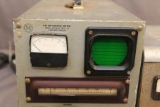
I picked up a junked Radio Specialty Mfg. FM Deviation Meter for $10 that still had most of the parts in it (including all the tubes!). I checked around for a schematic, but the only info I could find was that others were looking for the same schematic......so I tore it apart (a couple weeks of just desoldering.......).
I'd like to do something with the transformer but I'm not sure how to approach it.
I set the variac to 122vac (my nominal local potential) and did some no-load measurements on the secondaries and got:
825v CT
895v no CT (?!?)
91v no CT
65v no CT
7v CT (heaters)
5.6v (diode heaters)
I've been playing with 895v secondary on PSUD II and have pretty well come to the conclusion that there really isn't a practical use for 1270VDC (unless I maybe want to build a radio transmitter......).
Ideas welcomed, BTW.
I'd really like to somehow center-tap it so I can split pre+driver and output plate duties between the two high voltage secondaries.
I'm familiar with the technique of using equal resistors in series across the heater circuit to lift the heater voltage, but I'm pretty sure I read a long time ago that though it should only be used for heater circuits and (I think) NEVER used for plate voltages. I've searched the internet with every potential search term I could think of and can't find that reference.
So I guess my question would be: Why can't (or why shouldn't) a faux center-tap be used on the high voltage secondary (Safety? Explosion? Alternative dimensional travel?).
If it turns out that there actually is a way of doing it would it be connected to the center-tap of the heater circuit and/or chassis ground?
Or is this just wishful thinking and I'd be better off just not wasting my time trying to do something that isn't practical or impossible (and cheap).
One think I already thought of is using a 1:1 transformer with a center-tap but I'd rather just use the other high voltage secondary than go that route. It might limit what I can do, but that's half the fun......
> Why can't (or why shouldn't) a faux center-tap be used on the high voltage secondary
You waste far more power in the resistors than you can get out of the scheme. ("CTing" a heater winding, we aren't trying to get power from the CT, just drain stray voltage.)
That "Meter" has a CRT 'scope. THAT'S why it needed 1,200VDC. At just a couple mA. There is NO use for this in audio, really in any non-CRT work. (Maybe a very heavy Geiger counter.) Certainly can't warm a '813.
The Deviation Meter is not much more than an FM radio. You can maybe power a preamp, but not more than a couple Watts of power stage. Even that would require an unlikely high impedance output transformer.
Attachments
Or is this just wishful thinking and I'd be better off just not wasting my time trying to do something that isn't practical or impossible (and cheap).
Bingo, you nailed it.
In practical electronics design, what you're asking to do is simply not possible.
PRR's post sums it up nicely.
It is an *oscilloscope* winding. The design load is just a few mA.
Seriously not good for anything audio.
Pretend we did have a use for 800VDC at 2mA. What choke value is minimum to ensure choke-input action?
Currentmin. (in milliamps) = VIn (RMS) / L (in henries)
L (in henries) = VIn (RMS) / Currentmin. (in milliamps)
L = 895V / 2mA = 448 Henries
500H @ 2mA is not a common choke.
- Status
- This old topic is closed. If you want to reopen this topic, contact a moderator using the "Report Post" button.
- Home
- Amplifiers
- Power Supplies
- Faux center tap on transformer secondaries