Oh! I see that now. Now I feel silly LOL.
So like this then?
 that's it.
I'll look in later.
The cap peak currents will be high... you need really good caps for this.
The doubler section has been built and used several times. I use Kemet PEH534 for the 470uF caps, and surplus Nippon-Chemicon for the 3300uF.
For the quad, I'll be using Chenxing. Wish me luck
")

Ok so it's working fine, but as you said, the caps need to be higher value I think... I'm only getting 460V at the filter under load... I can change 33u for 220u and see I guess, but it's working well enough since I don't need all the voltage the driver would swing if it had the right plate voltage.
Ok so it's working fine, but as you said, the caps need to be higher value I think... I'm only getting 460V at the filter under load... I can change 33u for 220u and see I guess, but it's working well enough since I don't need all the voltage the driver would swing if it had the right plate voltage.
reasonable imho...
c6/c9 is chosen in consideration of load currents, and how much ac is allowable to be lost across those caps with load, whereas c7/c8 is chosen on the basis of ripple voltage targets.....load currents is the important consideration in both cases...
Ok so it's working fine, but as you said, the caps need to be higher value I think... I'm only getting 460V at the filter under load... I can change 33u for 220u and see I guess, but it's working well enough since I don't need all the voltage the driver would swing if it had the right plate voltage.
Yes, they need to be bigger. 220uF seems to work OK but I would seriously consider adding some resistance as I mentioned earlier. These doubler/trippler etc arrangements are used a lot in low voltage equipment like CD players to generate voltages for displays and so on and its surprising how often caps fail.
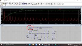
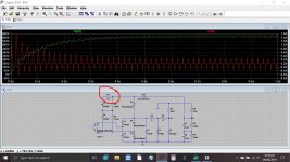
Look at the peak current here in the (now) 220uF's with and without a little added resistance. Current is at the right. Same goes for the 470uF's. Even a little resistance should greatly ease the stress on the caps.
Attachments
Some tips and remarks:
For an optimum efficacy, the input capacitors value (C1, C2, C6, C9) should be matched to the transformer's leakage inductance: this will give you the highest output for the smallest capacitors.
Try to measure the transformer's parasitic parameters.
If you place L1 directly in series with D4, your output voltage will be the average rather than the peak, which will cause a severe reduction, because in addition a component of the input voltage is halfwave rectified.
If your initial voltage was much too high, that is certainly OK, otherwise you will end up much lower than expected
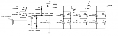
Ok, so I made one final change. I now have 580V instead of 450V. Nice! When all is said and done though, It's cheaper to use the DC-DC board than buy all the caps, and the choke, but it's a nice solution if you don't want to use SMPS
Attachments
Last edited:
That looks a pretty decent final version to me. Make sure the high value resistors are rated for high voltage use (I'm sure you know all this ) because although the power dissipation is relatively low, it doesn't mean that any 0.5 or 1 watt part will be OK. Resistors have voltage ratings as well as power ratings.
) because although the power dissipation is relatively low, it doesn't mean that any 0.5 or 1 watt part will be OK. Resistors have voltage ratings as well as power ratings.i thought ac had no polarity, i will try that both ways and see...
It doesn't in that sense.
In this circuit the top winding connects via all those 470uf caps to ground which means there is no AC voltage on that top winding when measured with respect to ground.
The lower winding connection is the one with the full AC present (with respect to ground).
Yup... Equalizing resistors are 1/2W rated at 350V, R11 and R12 are 5W and rated for 1kV. I've honestly never has an arc across a resistor though, but this is the highest voltage I've needed to use.
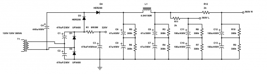
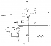
This is what it's powering (one for each channel):
Yes, I know, the following 51k grid resistors are too low, but this is a retrofit and I haven't needed to change them yet.
This is what it's powering (one for each channel):
Yes, I know, the following 51k grid resistors are too low, but this is a retrofit and I haven't needed to change them yet.
Attachments
Last edited:
kodabmx, are you going to drive a pair of large DHT's?
Best regards!
Nope. Just a 12SN7 driver. I posted it above.
Elvee: Good information for the next build (I'm sure this won't be the last time I use this circuit).
- Status
- This old topic is closed. If you want to reopen this topic, contact a moderator using the "Report Post" button.
- Home
- Amplifiers
- Power Supplies
- Voltage doubler/quadrupler