This is a typical reply from a manipulative narcissist. I refuse to be manipulated.Some anecdotal evidence, just to brighten up this amusingly theoretical discussion")
Why are you using humiliation as a means of persuation?
Last edited:
(speaking hypothetically here) Interesting point about dynamics through a regulated supply... I wonder how many regulators have tens of thousands of uF of capacitors AFTER the series pass element (as well as before) so that the power amp can still draw HUGE INSTANTANEOUS currents directly ....
Not many I'll warrant!
I suspect you might get some benefit if you pay attention to the above.
By which time you'll have so much C on your power supply you could do away with the regulator anyway!!
Normally a good reg has less Rout than the caps so the caps don't do a lot. Just a bit for stability is enough.
That's just over 60dB. At 1kHz.
Before NFB. We often find >40dB NFB available in the lower audio band. So ripple may be 100dB in the lower audio band. This IS the OoM of ripple we find in rather ordinary commercial power amps. (Two random Crown and Peavey: 107-109dB S/N.)
Go to 10k and you loose another 20dB.
I assume you mean 10kHz (I initially thought you mean driver impedance). You assume the leakage is capacitive. That is not what my model says (no change at 10kHz or 100kHz). I agree that models can NOT be trusted. However they usually have values for capacitances. Counting on thumbs, the C of a moderately large device is not large compared to an 8 Ohm load.
A further point: We traditionally feed electronics with large rail capacitors. Unless there is some HF crap-source more powerful than wall-power, the crap on the rail has a strong tendency to go *down* with frequency (at least inside the audio band).
OTOH, many high-NFB amplifiers stability compensate with a small cap from output to a base referenced to a rail. The PSRR of many opamp chips goes to about zero at 1MHz, so may be only 40dB at the top of the audio band (but 80dB before NFB at power frequency). In discrete work we sometimes add a filter to this stage.
To be fair, the 'crap' probably goes down with lower output also.
4V peak ripple would only happen at FULL output (and with cheap filter caps). 10X less at small outputs.
The PSRR would not change much, as long as the idle current is set high enough for clean reproduction of small signals.
_____________
The primary objection to regulation is that you can't get full use of the raw DC you bought, and you roughly double (maybe 1.5X) the amount of large devices and heatsinks you need to make a given power spec. (Though you may be able to use cheaper devices.) Your Product Manager won't like that, because Brand Y has adequate specs at a lower price and will eat your lunch. Of course in DIY you don't have to use such a sharp pencil. Still most of us struggle with the budget (and complexity).
Some types of "exotic" amplifiers like SE, class A, tube, etc do not like dirty supplies, but for a reasonably designed, run-of-the-mill SS PP class AB amp, a good rejection comes almost for free provided you have done your homework.
If it does not, the first thing to do is to ask why and fix it (the proper way), not throw a super-clean supply at it.
If an amp is incapable of rejecting supply nasties, it is probably the symptom of deeper flaws.
Of course, any amplifier will always work (very) marginally better with perfect supplies, but that is certainly not a good reason to indulge in such an extravagance
That's one reason why I am going to regulate. Another is (and it may seem silly) is because I can. There aren't a whole lot of areas where, as a DIYer, you can afford to do something that the major manufacturers cannot. And this is precisely that! It's too expensive for them to add parts that may not improve their spec sheet. I believe it WILL improve the sound, although it may not be much; but my amp will be like no other!A non-regulated supply not only has mains ripple but also all kinds of noise and junk coming in through the mains and the mains transformer. A good regulator makes short shrift of all that junk, which can significantly improved the sound. Some amps benefit more than others but it always helps. Jan
My understanding is they are for smoothing, local decoupling close to the output devices is for instantaneous current demands(speaking hypothetically here) Interesting point about dynamics through a regulated supply... I wonder how many regulators have tens of thousands of uF of capacitors AFTER the series pass element (as well as before) so that the power amp can still draw HUGE INSTANTANEOUS currents directly ....
Not many I'll warrant!
I suspect you might get some benefit if you pay attention to the above.
By which time you'll have so much C on your power supply you could do away with the regulator anyway!!
Most regulators have an inductive output impedance. Adding capacitance in parallel with this raises the impedance, thus making things worse. In some cases the degradation will be so bad as to be audible, but it is likely to be perceived as an improvement because everyone knows that slapping huge caps on is a good thing to do. Everyone but those who actually understand electronics.
To come to the practice:
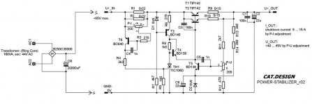
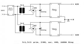
I built this power amp in the late 1970s: ( https://www.diyaudio.com/forums/solid-state/96192-post-solid-pics-512.html#post5036286 ) with regulated power supply.
The reason for this was already purchased power amp boards with a simple circuit concept; e.g. without current sources etc. in the preliminary stages, quasi complementary output devices; and with a not well functioning overload protection.
I have removed the overload protection of the power amplifiers and instead equipped the power supply control with an overcurrent shutdown. The transformers were also already bought and at that time I wanted to make something out of the existing material.
Compared to an unregulated power supply with only rectifier and capacitor, the power supply control for this amplifier provides a significant improvement in performance and sound quality.
Here the circuit:
Attachments
- Status
- This old topic is closed. If you want to reopen this topic, contact a moderator using the "Report Post" button.
- Home
- Amplifiers
- Power Supplies
- High Voltage Regulated Power Supplies for Power Amplifiers