Hi Knuth,
You mean how much capacitance can the SMPS be loaded with?
Many SMPS have a charger characteristic which means they act like a current source below the nominal voltage and regulate the voltage below the current limit. My experience is that such SMPS can take almost any capacitance.
You mean how much capacitance can the SMPS be loaded with?
Many SMPS have a charger characteristic which means they act like a current source below the nominal voltage and regulate the voltage below the current limit. My experience is that such SMPS can take almost any capacitance.
Thank you for your answer. But if it is the inrush current that is the problem, have you any advice?
24V/5A is about 125W. Does the 125W SMPS blow the main fuses at start-up? What other inrush problem would you have? Too large capacitor surge current at start-up?
Thank you for your answer. But if it is the inrush current that is the problem, have you any advice?
In my experience adding big capacitance on output of SMPS can make it go into over current protect mode and shut down.
SMPS is not like a normal power supply, it doesn't need 1000's of uF on the output. Its running at a much faster frequency so needs much less.
I have not tried it yet.
So I guess the best solution would be a < 100 uF capacitor at the input of the capacitance multiplier, which has a reasonable time constant for the filtering.
100uF may give a sufficient time constant if you use a FET in the capacitance multiplier. Even with a bipolar transistor, the time constant may be sufficient.
The problem I foresee is if the ripple on the SMPS output will cause the FET/bipolar to saturate in which case even a fine time-constant will be of no use.
The problem I foresee is if the ripple on the SMPS output will cause the FET/bipolar to saturate in which case even a fine time-constant will be of no use.
Please clarify.
Please clarify.
Nynorsk or bokmål?
A capacitive multiplier is in principle an emitter (or source) follower. For an emitter/source follower, the base/gate needs to have a bias voltage AND the collector/drain voltage needs to be such that the NPN transistor/N-channel FET is in the active area and not saturated. If saturation is entered, the capacitance multiplication is gone with the wind.
Let's try to image the capacitance multiplier circuit with the values you indicate. We assume you have a FET with a Vgs of 4V (active) . If you use a FET, you only need a simple RC circuit to the gate to have 20V out. As long as the drain voltage is above some 20.5V, the FET is in the active area and the capacitance multiplication works. If the drain voltage drops below some 20.5V, the FET saturates and the load sees only the actual capacitance at the drain without multiplication. Why could the drain voltage drop below 20.5V? Because an amplifier with music is a very dynamic load perhaps demanding 100mA for a moment and short after several amperes. The FET can only get this energy from the SMPS or the capacitance at the output of the SMPS. Far the majority of SMPS are designed for pretty static loads and when the amplifier, through the FET, suddenly demands a high current, the SMPS cannot supply such a current imediately. Unless there is good capacitance at the output of the SMPS, the drain voltage will zag quite rapidly and the drain voltage may pass below 20.5V. We balance the step response of the SMPS with extra output capacitance at the SMPS in order to improve the dynamic response. I guess you will need some 2200uf-10000uF for a good step response.
With a bipolar NPN transistor, the saturation voltage will be in the same order (but of a different nature) while you need two resistors (and a capacitor) to have 20.7V at the base from a 24V supply. The base current puts a limit to the value of the time-constant resistors.
Was this reasonably clear or do you want me to make my explanation more dodgy in bokmål?
Was this reasonably clear or do you want me to make my explanation more dodgy in bokmål?
He, he , thank you very much!
Large capacitance on the output of a SMPS is next to useless. All the HF switching noise will go straight through it.
I have repaired and tested a lot of SMPS power supplies and most of the noise components are HF at the switching frequency or harmonics of the switching Hz. I have seen low frequency noise but this is usually induced.
I have 2 SMPS's on the bench now, both are 24V 1.5amp supplies, the first is an eBay cheapie and the other is from medical equipment I scrapped and whipped the SMPS out.
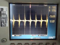
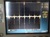
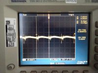
The cheap one has 38mVrms ripple at 166KHz the medical supply has 2.3mVrms ripple at 100KHz, I removed the output filter from the medical supply so both are unfiltered.
There are 2 ways you can go about filtering SMPS noise.
Firstly you can determine the switching frequency and build a LCR lowpass filter at say 1/4 of the switching frequency.
The best way IMO is to use a filtered buck converter then a LDO after the buck to filter any low frequency noise.
I have repaired and tested a lot of SMPS power supplies and most of the noise components are HF at the switching frequency or harmonics of the switching Hz. I have seen low frequency noise but this is usually induced.
I have 2 SMPS's on the bench now, both are 24V 1.5amp supplies, the first is an eBay cheapie and the other is from medical equipment I scrapped and whipped the SMPS out.
The cheap one has 38mVrms ripple at 166KHz the medical supply has 2.3mVrms ripple at 100KHz, I removed the output filter from the medical supply so both are unfiltered.
There are 2 ways you can go about filtering SMPS noise.
Firstly you can determine the switching frequency and build a LCR lowpass filter at say 1/4 of the switching frequency.
The best way IMO is to use a filtered buck converter then a LDO after the buck to filter any low frequency noise.
Last edited:
Here are a couple of photos of the output noise of the 2 supplies. Supply 1 = eBay supply and S2 = good medical supply
Pics in order,
S1 no filtering, S1 100nf to mains ground, S2 no filtering
Pics in order,
S1 no filtering, S1 100nf to mains ground, S2 no filtering
Attachments
I found another thread:
GB for Simple Cap-Mx Regulated Low-Noise PSU
Could I use something like this (post 1)?
GB for Simple Cap-Mx Regulated Low-Noise PSU
Could I use something like this (post 1)?
I don't understand the original question. First, a 'capacitance multiplier' does not multiply capacitance; it is merely a CR low pass filter followed by a simple power buffer.
The SMPS will not see any extra capacitance, as it just sees the R of the CR.
If the SMPS can handle the peak current then all will be well. A 5A PSU feeding two Class A amps with 1A quiescent current drain should be OK. The 'cap multipler' will merely filter out some SMPS noise. If the SMPS cannot handle the peak current then no amount of 'cap multiplication' will make any difference.
Referring to post #15:
It is the solution with the CLC-filter and capacitance multiplier I was thinking of.
A while ago at work I put a Panasonic FM 1000uF 50V at the Meanwell 200W 24V SMPS but the FM goes pop. I guess 1000uF is too much for the SMPS. I think lower uF polymer electrolytic might be more suitable.
You could start with a 100uf then step it up until the SMPS complains.
Then step back a bit and use that.[/QUOTE
What about LF current draw by the amplifier?
What about LF current draw by the amplifier?
The SMPS provides very fast output pulses so LF isn't a problem.
The cap is re-charged so quickly it doesn't matter.
- Status
- This old topic is closed. If you want to reopen this topic, contact a moderator using the "Report Post" button.
- Home
- Amplifiers
- Power Supplies
- SMPS - Capacitive loading