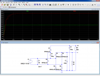
I'm having some trouble implementing the following schematic:
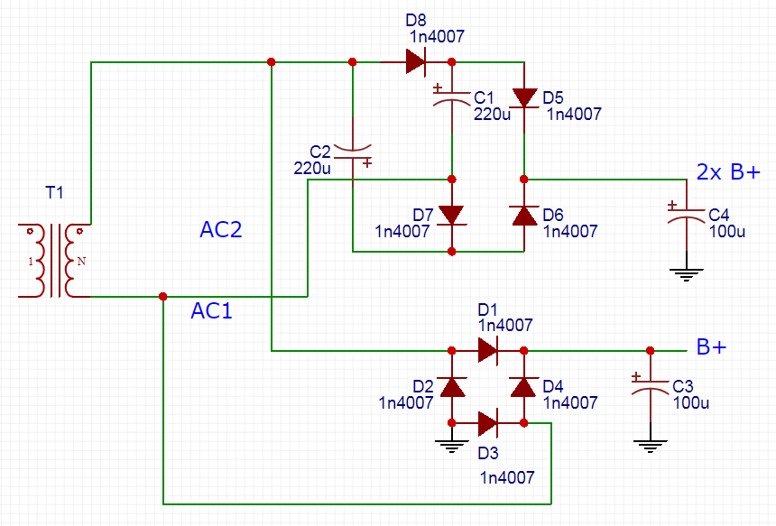
I found the above in a schematic posted by Tubelab who was using it in a scrap box amplifier (powering heaters on B+ and screens with the 2x B+ I believe). I had a small PCB made for my purpose.
I get the expected voltages with a 12V PT and no load, but something is going wrong when installed with a 15VA 115V isolation transformer (I have verified unloaded AC voltage). The voltage droops and the PT starts heating up, this is without tubes installed.
In my build the ~150V B+ feeds a CLC filter and 40mA draw (transformer loaded tubes) and the ~300V 2x B+ feeds a MOSFET regulator with around 10mA load draw (low current phono circuit). I am testing without tubes and the regulator disconnected though.
The caps are all 250V rated. I've used bridge/Delon doublers in the past and with those, rating for 1/2 the doubled B+ (plus safety margin) is enough. But does that hold true with this doubler variation? In trying to wrap my head around the circuit, it still looks to me like the caps are charged to peak AC and standing on top of one another. Then again, a shorted cap might explain what I'm seeing (but no visible damage to the caps).
I've made plenty of dumb wiring mistakes before, but I'm not finding one here so I'm hoping someone else can double check the theory of this circuit.
Posting to the tube form because it seems to be a useful circuit for tubes IF I CAN GET THE DARNED THING TO WORK!
edit: link to the post where I found working version of the schematic https://www.diyaudio.com/forums/pow...econdary-parallel-question-3.html#post5427220
Last edited:
AFAIK all multiple tapped doublers of all types collapse when current draws from the taps are not matched.
This is what I believe I've read elsewhere but I don't have experience to back it up.
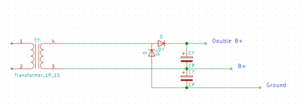
An alternative solution to what I'm trying to do is here:
Tube Power Supply PCB
This uses a single winding but requires a center tap. Part of my goal was to use cheap and widely available isolation transformers to get multiple voltages. A transformer with a 230V CT secondary may work, but I'm still curious about the schematic in the OP.
It works at least according to Tubelab. I'll try to dig up the discussion where I found it.
edit: here's the post and schematic in quest: https://www.diyaudio.com/forums/pow...econdary-parallel-question-3.html#post5427220 claims to be working amplifier
Last edited:
The circuit in post 1 looks fine to me. None of the newbie errors we usually see when someone tries to run two PSUs off one secondary.
I am going to guess that you have one of the caps reversed. This would be just about OK on low voltage but would show up on high voltage.
15VA is a bit too small for this, as you are expecting to draw 9W DC.
I am going to guess that you have one of the caps reversed. This would be just about OK on low voltage but would show up on high voltage.
15VA is a bit too small for this, as you are expecting to draw 9W DC.
I think the OP schematic is an attempt at a full wave doubler.......It cannot work with full wave bridges.
I have built several of these and they DO work. The amp shown in the schematic that is linked in post #6 is still alive and well as built about 8 years ago.
I see two possible issues.
The caps are all 250V rated.
This circuit will produce 330 to 350 volts in normal operation depending on line voltage and the fact that isolation transformers are not actually 1:1. It may produce quite a bit more unloaded if your live voltage is distorted or noisy. C4 should be a 400 volt cap. All the others can be 250 volts.
The current in any rectified power supply is drawn in short pulses at the peak of the AC cycle. Use of tube rectifiers blunt this peak somewhat, but this circuit uses silicon. On any given peak there are two diodes feeding hungry caps in parallel in this design since it is essentially two power supplies on one transformer. A small power transformer may be operating near saturation when operated into a resistive load, and may overheat when feeding rectifiers. This should not happen with no load at all though.
I have found that an isolation transformer needs to be derated a bit when feeding diode rectifiers. I tend to suck no more than 35 watts from a 50 VA Triad N-68X when using diode rectification. The amp design shown in the link on post #6 used a 100VA isolation transformer to feed a guitar amp that draws about 40 watts at idle and 70 watts at full power (17 watts output).
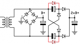
Drawing it a little different makes it more easy to understand.
That's how my original schematic was drawn. It's the HBAC_5T schematic linked in post#6, a 5 tube guitar amp with 100 mA series heaters.
To prevent charging the capacitor in the wrong direction....With two diodes you can use the same value for all.
I never noticed any reverse charging, but then I didn't look too hard. I have an LT spice sim on a backup drive somewhere. My application has a constant load on the FWB (the tube heaters), but the doubled output is very lightly loaded (about 2 mA) until the tubes are conducting. Extra diodes are cheap insurance.
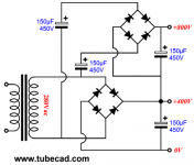
Why not use a voltage doubler.
That circuit (post #2) will make the power transformer very unhappy (buzzing and heat) if the loads drawn on each half cycle are different. This means that very little current can be drawn from the B+ supply.
It's described quite well in the best voltage doubler -the 4X8!
Great link, thank you!
@Tubelab_com
I was hoping you'd chime in here. Thank you for confirming this works.
Thanks to everyone else for confirming the doubler isn't the culprit. Like I wrote earlier, I'm not immune to dumb wiring mistakes...
I did a little more poking around this morning and found an issue with a gyrator (anode load) board down stream that may have something to do with my issues. It was in the circuit initially until I saw there was a problem and I then disconnected it before troubleshooting the doubler circuit.
The gyrator's FET tab/drain is shorted to the chassis, dumping the B+. I suspect this may have damaged the PT (I never saw smoke, but I did smell something funny at one point). Even though the gyrator is now out of the circuit, the B+ is still measuring low (and slowly drooping) though unloaded.
Sound like I killed the PT to anyone else? Is there a good way to test this other than taking it apart and looking for damaged windings?
I pulled my build apart and retested everything (the way I should have the first time).
The PT measured fine unloaded, so I rebuilt a fresh doubler PCB with new diodes/caps. That measured correctly unloaded (both rails) and didn't droop. This board was definitely part of the issue.
I hooked up the voltage regulator (it's a LR8 + MOSFET type) and that measured bang-on. Lastly I replaced the MOSFETs in my gyrator anode load PCBs and re-mounted them, triple checking that they weren't shorted to the chassis. After dialing in my gate voltage, everything measures as it should!
I think the gyrator boards were the culprit that took out the rectifier/doubler PCB. They were on insulators (mica), but I must have over-tightened the screws and/or had some aluminum tear out on the back of the hole. I hit the back of the panel with some sandpaper before remounting and didn't crank down so hard on the screws.
Thanks all for the help in narrowing down the issue.
- Status
- This old topic is closed. If you want to reopen this topic, contact a moderator using the "Report Post" button.
- Home
- Amplifiers
- Power Supplies
- Bridge rectifier and voltage doubler from a single PT winding w/out CT?