I'm not quite sure how to deal with a stereo circuit when modelling.
It's important, I'm sure, to account for all the current sinks in the circuit ( in my case, it's a stereo 2-stage SE tube amp ).
After the filter, where the PS splits into two rails(?), should I double the theoretical current draw for constant current source representing the tubes into 1 constant current sink for finals and one for driver? Or should I model it as a mono and somehow calculate the load on the PT?
I apologize, I've looked, but can't find instructions on how to do this.
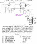
For example, I am using this schematic; http://www.pmillett.com/tubebooks/Books/Atwood/Robin%20&%20Lipman%201947%20Practical%20Amplifier%20Diagrams.pdf See "3 tube 3 watt DC coupled amplifier" page 6 of the book. But this is from 1947, so it is mono.
lt has a CLC filter (or is it CLCRC?), then I inserted an 86mA constant current source tap representing both finals (makes sense) but then the PS splits through two dropper resistors. How do I account for all the components and driver CCS that come AFTER that split? I don't think I want to calculate parallel R's and C's because I don't think that would give me true voltage and ripple current seen at each tube. But if I DON"T account for R's and C's and double up on the CCS, then the PT results won't be accurate.
I'm sure I'm missing something simple, since I can't find any other threads with this question.
It's important, I'm sure, to account for all the current sinks in the circuit ( in my case, it's a stereo 2-stage SE tube amp ).
After the filter, where the PS splits into two rails(?), should I double the theoretical current draw for constant current source representing the tubes into 1 constant current sink for finals and one for driver? Or should I model it as a mono and somehow calculate the load on the PT?
I apologize, I've looked, but can't find instructions on how to do this.
For example, I am using this schematic; http://www.pmillett.com/tubebooks/Books/Atwood/Robin%20&%20Lipman%201947%20Practical%20Amplifier%20Diagrams.pdf See "3 tube 3 watt DC coupled amplifier" page 6 of the book. But this is from 1947, so it is mono.
lt has a CLC filter (or is it CLCRC?), then I inserted an 86mA constant current source tap representing both finals (makes sense) but then the PS splits through two dropper resistors. How do I account for all the components and driver CCS that come AFTER that split? I don't think I want to calculate parallel R's and C's because I don't think that would give me true voltage and ripple current seen at each tube. But if I DON"T account for R's and C's and double up on the CCS, then the PT results won't be accurate.
I'm sure I'm missing something simple, since I can't find any other threads with this question.
> should I double the theoretical current draw
I have a recipe that feeds one person. I need to feed two. Yes, of course you double the meat, potatoes, and milliAmps. Double the choke mA and cap uFd.
Your amplifier is NOT a "constant current". And ideal CCSes act funny and upset simulation. A tube acts a lot more like a resistor than a CCS. If you double the voltage, the current is not the same, it at least doubles. Figure your load as-if it were a dumb resistor.
There is NO good point in modeling past the C-L-C section. The R-C droppers for the driver were figured out in 1947 and Ohm's Law has not changed.
I'm not real sure why you need to sim it at all. AH! No inductance is given for the choke. I'd eye-ball 3H to 5H for stereo.
Attachments
- Status
- This old topic is closed. If you want to reopen this topic, contact a moderator using the "Report Post" button.