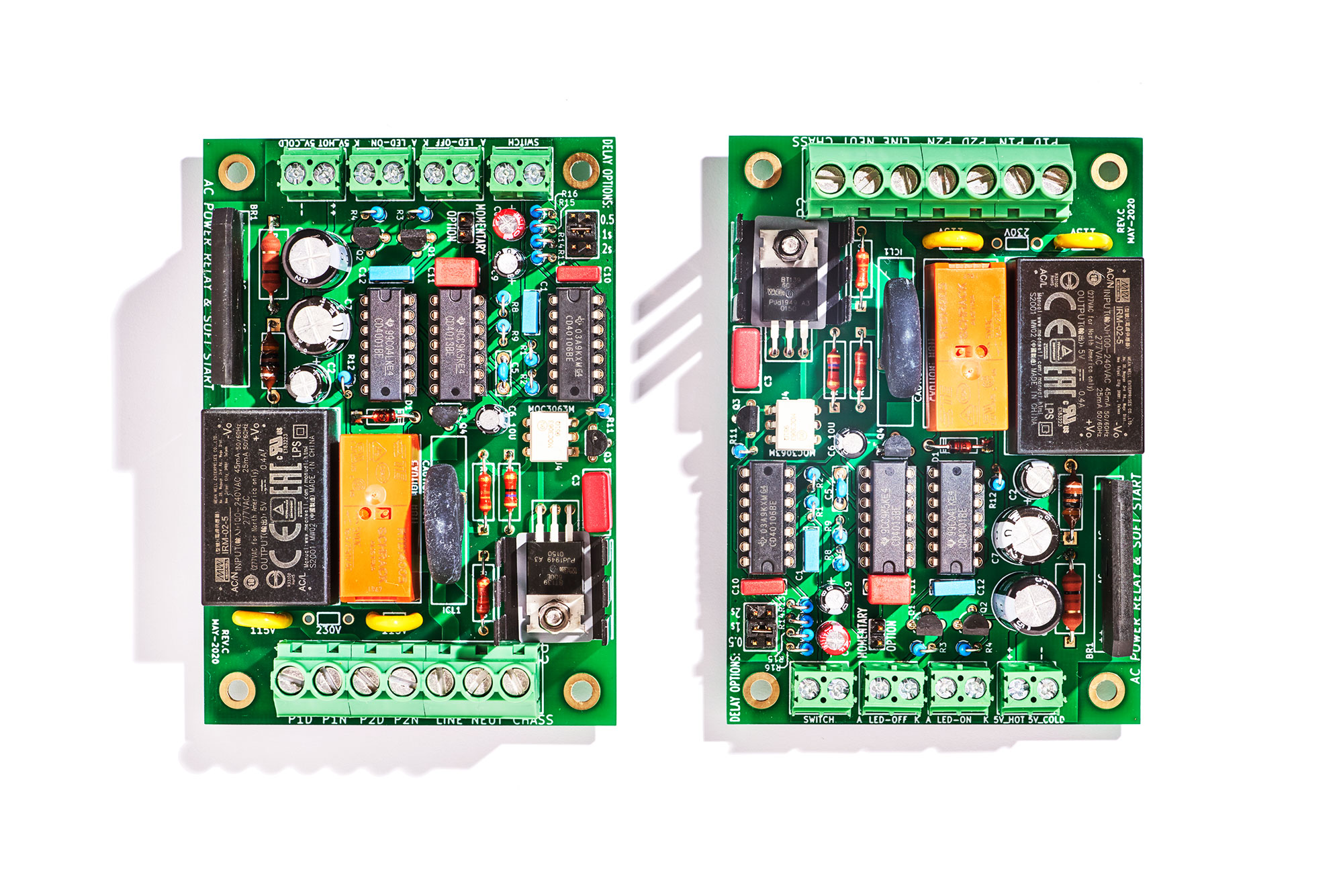
In my opinion the PIC is a great idea ... if you don't mind providing technical support for the software. The soft start board I just built (photo below), uses discrete logic ICs, but the number of external I/Os needed is small: just 1 digital input and 5 digital outputs. So all of the digital logic could be implemented using a single DIP-8 uC like the PIC 12F1571 ($0.64 qty=1 at DigiKey). However, I determined that I certainly do not want to provide technical support on software. So I used hardwired, discrete logic ICs instead. And my PCB grew larger. Imagine how much smaller the PCB could be if those three CD4000-family logic chips disappeared!
_
_
Hi all . This topic is interesting to me ,and i would like to share my solutions ,so here are my few cents .
For my diy amplifier (2x ~100W 8Ohm ) i tried two versions of power supply , toroid ~360W and smps +-45V 500W from ebay , and guess which one have i chosen ... SMPS . Less output voltage drop no-load - full load 8 ohms ,less 100hz ripple on output (high frequency ripple small in comparing to 100hz). The SMPS itself has no NTC ,no soft start circuits , so i needed one . I used arduino for this , 47ohm 50W resistor for soft start itself ,switching is done by 20amp SSR relays 2pcs , one for resistor ,second for full power . Also i have implemented a 5 minutes power-off when no signal present ,and automatic turn on with soft start sequence when signal appears .Used arduino internal ADC inputs for
signal monitoring .Also AC power after power swith is monitored with optocoupler ,so if you turn off power ,or AC gets lost ,signal gets muted first ,then speakers turned off . For speakers turn off used SSR also ( IRF1407 x 8 pcs per channel ,small dual isolated output inverter for powering mosfet gates ).
No longed using power switch at all and no clicking sound ! Standby power compsumption less than 0,5W ,can't remember how much exactly ,small old phone charger used for supplying arduino .So it's ok for me ,working fine for about two years .Arduino pro mini board used (without usb socked ),but any version will do this job. Few days ago have made new pcb for SMPS (spare unit),and integrated two BTA16-800 and moc3083x for remote turn on and soft start of smps .The same solution can be used for traditional transformers .
Previously have made analogue board with LM339 ,two comparators used for signal detection ,one for 5-minutes power off delay and one as repeater ,and two mechanical relays ,but have tired of relay clicking sound") If anyone is interested ,i can share more details , just ask me .
If anyone is interested ,i can share more details , just ask me .
For my diy amplifier (2x ~100W 8Ohm ) i tried two versions of power supply , toroid ~360W and smps +-45V 500W from ebay , and guess which one have i chosen ... SMPS . Less output voltage drop no-load - full load 8 ohms ,less 100hz ripple on output (high frequency ripple small in comparing to 100hz). The SMPS itself has no NTC ,no soft start circuits , so i needed one . I used arduino for this , 47ohm 50W resistor for soft start itself ,switching is done by 20amp SSR relays 2pcs , one for resistor ,second for full power . Also i have implemented a 5 minutes power-off when no signal present ,and automatic turn on with soft start sequence when signal appears .Used arduino internal ADC inputs for
signal monitoring .Also AC power after power swith is monitored with optocoupler ,so if you turn off power ,or AC gets lost ,signal gets muted first ,then speakers turned off . For speakers turn off used SSR also ( IRF1407 x 8 pcs per channel ,small dual isolated output inverter for powering mosfet gates ).
No longed using power switch at all and no clicking sound ! Standby power compsumption less than 0,5W ,can't remember how much exactly ,small old phone charger used for supplying arduino .So it's ok for me ,working fine for about two years .Arduino pro mini board used (without usb socked ),but any version will do this job. Few days ago have made new pcb for SMPS (spare unit),and integrated two BTA16-800 and moc3083x for remote turn on and soft start of smps .The same solution can be used for traditional transformers .
Previously have made analogue board with LM339 ,two comparators used for signal detection ,one for 5-minutes power off delay and one as repeater ,and two mechanical relays ,but have tired of relay clicking sound
If anyone is interested ,i can share more details , just ask me .i have implemented a 5 minutes power-off when no signal present ,and automatic turn on with soft start sequence when signal appears .Used arduino internal ADC inputs for signal monitoring.
This is right in line with what I'm trying to implement.
I've been digging into very low powered stuff, like opamps that hardly draw anything and a supply with a battery that keeps it running in case the mains go down, but still the psu is up as long as there is mains, but with super low power, like about 1W or less, and it keeps the battery charged as well.
How did you implement the signal sensing to feed that in the arduino adc?
Anything you care to share?
Also AC power after power swith is monitored with optocoupler ,so if you turn off power ,or AC gets lost ,signal gets muted first ,then speakers turned off.
More or less what I'm aiming for, except for one thing, there would be no off-switch at all on my system, so it's 100% signal driven. If signal isn't there for a few minutes, then an orderly total shutdown is done, sequentially, and it goes into very low power standby, sensing for signal. When signal shows up, then proper sequential power up of everything, which is quite a bit in a 4 way multi-amp system, with the 4 way filters and all..
Standby power compsumption less than 0,5W ,can't remember how much exactly ,small old phone charger used for supplying arduino.
That's what the full standby power usage is?
If anyone is interested ,i can share more details , just ask me .
I definitely am!
I'm always looking at other methods and whatever others come up with that's much more clever than what I found.
A cheap and simple soft start which I use which is non invasive; IE.no relays,electronics etc. is a 470 0hm 20 watt resistor and non latching push switch which bypasses the mains switch while operated.Measuring the voltage on the reservoir caps showed it took approx. 3 seconds to reach about 90% of final voltage when mains switch is then operated.
So , additional details .
About power compsumtion in standby.I've had several old switchmode phone chargers, i remember it was about 6 volts one ,(maybe old nokia ?) even without capacitor on 300v bus ,and i've measured AC current (~240v AC) with no load ,and chose with the lowest , if i remember correctly ,it was ~0,8 ma .Also for arduino boards,like uno or nano , AMS1117 voltage regulator is crappy ,noisy and consumes itself some current ,and not even close to LDO - i replace it with LDL1117 ,same pinout ,voltage drop 30mv on arduino uno board ,look at its datasheet ,have found it on arrow.
Audio inputs to arduino done through 10k resistor ant 100nf each channel (L R ) to seperate ADC inputs ,also 1nf caps to gnd , and 270k each to virtual ground 2,5v voltage divider . Similar to single supply opamp inputs schematic .Third ADC input monitors virtual ground 2,5V. Code checks for difference on any input in refence to virtual ground (digital value about 500-512) .Any value ,less or higher ,will trigger .But because of noise of internal ADC , i've had to chose value 4 for false triggering (about 20mv sensitivity ). A change in value higher than 4 results in 5 minutes timer reset and starts startup sequence if was in off state.
Amplifer still has AC switch on front panel ,but its always on ,also 2 color led , Red-standby , Green-operating .Tried to find switch like OFF-ON-ON , but no sucess , only found ON-OFF-ON switches ,so used simple on-off .
AC presence monitoring optocoupler pc817 is connected through diode bridge 1n4148 and 470k from mains (led side) ,transistor side goes to 1Mohm load and pnp transistor with 100k load and 10nf in parallel .Whis was for reducing current consumption from mains ,optocoupler is always operating , so led current must be minimal ,but still enough to tell arduino of AC present or not .
So amplifer has two smps ,one small for arduino ,works 100% of time ,and second one is more powerful ,and used for amplifer itself and speakers SSR relay (used aux 12v output). Speakers dc protection has not implemented yet ,just delay turn on and turn off sequence. Big SMPS consumes about 4W with no amplifier .
About 35W idle from mains ,when amplifier operating ,but no signal less than 5 min . After 5mins is only arduino left powered on and mode led . PS. you can cut power led or resistor for power led from arduino board ,and change voltage regulator to less consuming one - big change in standby consumption . But in currently used arduino pro mini its sot23-5 voltage regulator ,don't know that regulator ,so i don't changed it .
I've remembered older version - with lm339 - it consumed ~0,1W in standby ... In arduino i've used some sleep library ,a some reduction in consumption too ,but at moment can't remember which one .But i still have the code on PC .
After looking at a bunch of soft start circuits I decided to design one according to my beliefs as to what is the best way to do it. It may be completely different from your beliefs but there it is.
I wanted a separate power supply for the soft start circuit so it could be used to turn the amp on and off and the powering up of the amps large transformer would not interact with the circuit. The transformer has a dual primary so it can be used for 115 and 230 VAC. There is a surge suppressor, R1, across the transformer input as well as a small high voltage capacitor to filter out RFI on the line from coming into the amp. The power supply always draws a few milliamps, it powers a multicolor LED that emits red with the amp in standby.
The on/off switch only switches 15 volts DC at very low current so you don’t need a switch that can handle large AC current in-rushes. When switched on, the DC power is sent through a regulator for consistent voltage and time of circuit operation. Relay K1, a small current relay, pulls in and turns on a triac, AC current flows through a couple thermistors in series to limit in-rush current, two 5 Ohm parts for 115 volts to limit the current to no more than 12 amps, or two 10 Ohm parts for 230 volts also limiting to 12 amps. There is a current limiting resistor, R2, at the triac gate and a RC network,R3/C2, over the triac for some protection of the triac.
The circuit uses a voltage comparator, U2, to delay turn on of a relay, K2, which bypasses the thermistors, I do not like to have a current limiter staying in the circuit or the heat they generate inside the amp. The voltage comparator has a voltage divider, R8/R9, to set the voltage at 10v as the reference voltage on the positive input. That voltage is compared to the negative input which has an adjustable resistor, R7, which limits the current charging the capacitor, C6, and the rate of charge therefore voltage ramps up quickly, a couple seconds to more than 10 seconds, for the delay. When the voltage on the negative input matches the positive input, the output is turned on. There is a diode, D4, across R7 to give a quick discharge path for C6 so the circuit can reactivate quickly, as in the case of a temporary power loss. R2 limits the current through the comparator which drives the gate of a small MOSFET through a gate resistor, R11. The MOSFET pulls current through a large relay K2 to bypass the thermistors and another small relay, K3, which changes the LED from red to blue to show status ON. There is a Zener diode, D5 and a small capacitor,C7, at the gate of the MOSFET to protect and stabilize it, probably not needed but cheap insurance.
So far, the circuit has been very reliable in a couple power amps with 2400VA and 4000VA toroid transformers with .78 farads to 1.2 farads of storage caps. In small part quantities the soft start board costs around $34 USD.
Attached is the Schematic, BOM and Gerbers. Enjoy.
I have a doubt can anyone clarify it? In the above circuit does the Triac starts at zero crossing point by default no matter when its triggered?
With no load at all on its secondary, a transformer shouldn't start up on zero crossing.
That's pretty much when it would cause the highest level of inrush current.
I think if there was only a transformer to power up, alone, it should probably happen at about 45degrees from zero crossing, which might have just about zero inrush current.
But reality isn't always perfect, but there is a best compromise to use.
However, sine a transformer is never "alone" in a power amp PSU, the load on it comes combined with the transformer's behavior and it gets complex.
With such a complex profile, it's very unlikely that powering up on zero crossing will be best, so there should be a delay after zero crossing before doing any power up.
There must be a sweet spot, where the inrush is minimized, within reason, and still the big cap banks in the PSU get charged up...
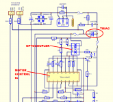
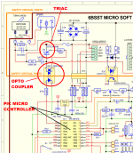
Those clever devils at Canadian high-end amplifier company Bryston, implemented soft start using a Triac and PWM. But, here's the clever piece, they piggy-backed upon the hard work done at Motorola (now ON Semiconductor), soft-starting big enormous electric motors. Yes, Bryston really did install a triac in their model 875 power amp, in series between the AC mains and the transformer primary. Yes they really did control the triac using a dedicated, special purpose motor controller IC called TDA1085C.
Bryston schematic attached below.
TDA1085C motor controller IC datasheet attached below.
Yes, really.
_
Bryston schematic attached below.
TDA1085C motor controller IC datasheet attached below.
Yes, really.
_
Attachments
This is old stuff already. They continued since and pretty much all their power amps have something like this, improved.
And they put DC blockers and ground lifters as well.
This is basically what I'd like to do as well. In addition to other things, using the same PIC, like DC sensing, short sensing on the speaker line, over-current sensing, etc...
And they put DC blockers and ground lifters as well.
This is basically what I'd like to do as well. In addition to other things, using the same PIC, like DC sensing, short sensing on the speaker line, over-current sensing, etc...
To answer whether a triac starts when a gate signal is present or does it start at the next zero crossing, from what I have read it starts at the moment the gate voltage is applied. The zero crossing situation is a red herring for a soft start, no matter where the sine wave is when you start, with discharged caps it will still have a large in-rush current. You need something to slow it down whether you PWM the gate of the triac or use NTC varistors, or some other method.
Last edited:
optocoupler like MOC3049 fires right just above the zero crossing the wave. Hence the inrush will be minimal. I think that can be a better move than complex programmed PIC. Well I dont deny using PIC or any controller but the application is just to start hence even when used with pulse triggering the Triac there will be considerable amount of noise getting modulated isnt it?
Triggering the Triac right at the zero crossing is unlikely to minimize inrush current, as it's not at zero crossing that the current is low. For a transformer alone it would be more like some 45degrees "after" zero crossing.
Now the transformer being loaded with something having a very different behavior (cap banks), the combined behavior will be different, and there is a sweet spot to find, a certain delay after zero crossing, to use before triggering the Triac, to minimize the inrush current.
Then after that, pwm will keep it going but under control. The pwm can be done in a way to give the transformer less turn on time at first, and then progressively over time to give it more and more, until it's fully on.
That is what would keep inrush current under control.
And one more thing about that opto-coupler detecting zero crossing, it can also be double used as a "loss of mains" sensor, for double duty, handled by the PIC.
Finding ex-techs from bryston is a tall order. I have no idea how I could do such a thing.
But we have a pretty good idea of what's being done. We don't know which time delay would be optimal for first turn on after zero crossing, but I suspect bryston did more than just calculate, they must've done some experimenting to fine tune that delay, which is all part of the PIC programming. Once this is known and properly applied, then it should all be running smoothly and fully controlled by program.
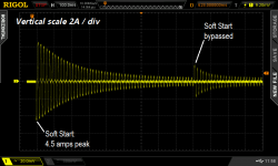
When you begin to actively experiment with soft start circuits embedded within large audio power amplifiers, complete with heavy power transformers and enormous banks of electrolytic filter capacitors, I think you'll enjoy the work tremendously. The number of possible options to explore is large, with many opportunities for innovation. To name one example: soft start bypass. Bob Cordell's power amp textbook discusses this in section 19.8, and Douglas Self's power amp book discusses it in Chapter 26. Pictured below is an experiment performed using US mains (115 VAC) and a 125 Joule Inrush Current Limiter device (P/N SL22-20007). The bypass event is clearly visible!
_
_
Attachments
Last edited:
When you begin to actively experiment with soft start circuits embedded within large audio power amplifiers, complete with heavy power transformers and enormous banks of electrolytic filter capacitors, I think you'll enjoy the work tremendously. The number of possible options to explore is large, with many opportunities for innovation. To name one example: soft start bypass. Bob Cordell's power amp textbook discusses this in section 19.8, and Douglas Self's power amp book discusses it in Chapter 26. Pictured below is an experiment performed using US mains (115 VAC) and a 125 Joule Inrush Current Limiter device (P/N SL22-20007). The bypass event is clearly visible!
_
Mark what happens when you try to turn on at zero crossing point. Do you have a graph for that?
A graph would be great to have. But this is highly likely to be different pretty much every time for every situation, with different cap banks, etc...
But if it was the transformer alone, with nothing to load it, it would be about 100% inductive and the core magnetization profile, which would mean turning on at zero crossing would be at the worst time, with maximum current.
Having cap banks at the other end though, changes things quite a bit, so the actual profile would be quite different from a simple transformer's.
A typical graph would still be nice to have to get a rough picture of how it works.
Emphasis added
When you begin to actively experiment with soft start circuits ...
Triggering the Triac right at the zero crossing is unlikely to minimize inrush current, as it's not at zero crossing that the current is low. For a transformer alone it would be more like some 45degrees "after" zero crossing.
Yeah. The transformer presents an inductive load at inrush when its magnetizing inductance needs to charge. In an inductor, the current is the integral of the applied voltage, so the current and voltage are 90º out of phase. This means that if you turn the current on at the zero crossing, you get the worst case inrush current.
Ametherm has an excellent note on how to design a soft start. Also the HP Journal from December 1982 is informative. I link to both in the References section of my Ultimate Guide to Soft Start Design. You'll likely find my guide useful as well.
Tom
- Home
- Amplifiers
- Power Supplies
- Yet Another Soft Start Circuit