Not Bad. Simple yet effective. Just need to find the right relay with the pull-in voltage that works. You still need a power switch that can handle the turn on surge even with the NTC limiting the current, so about 12 amps, not too bad.
With my soft start the on/off switch handles 40 ma @ 12 v and the relay that bypasses the NTC pulls in after the surge has passed, yes the circuit has a bit more parts then this one.")
With my soft start the on/off switch handles 40 ma @ 12 v and the relay that bypasses the NTC pulls in after the surge has passed, yes the circuit has a bit more parts then this one.
I was asked why such a big toroid transformer? The answer, lots of current capability and lower AC impedance/DC resistance. You want to have a capable power supply that will not voltage droop when the signal demands more current. A voltage droop will modulate the signal adding distortion. Lots of storage capacity in the capacitor bank also helps, bypass with film caps for better high frequency performance. And the lower impedance of the power supply seems to have a positive audible effect on the sound.
With lots of current you can have lots of output devices paralleled which gives you a lower output impedance which in turn has a better dampening factor for control of the speakers. Lots of output devices requires lots of current for idle bias to run class A and to lower higher order harmonic distortion products.
All of which makes for a heavy amp which most definitely will need a soft start circuit.
A voltage droop will modulate the signal adding distortion.
Not really. It will limit the max output level but that is seldom the issue. It does not lead to distortion unless the supply really collapses.
If you really want a stiff power supply that doesn't droop, put in a regulator. A good regulator help also to stop all that mains junk that often comes in through a toroid.
Jan
Hi,
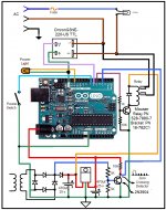
Sorry to discourage you but the best way to power up/down an amplifier in the same line with nigelwright7557 it is like me used the zero crossing to ramp the AC up when turning ON the amplifier and ramp the AC down when turning the amplifier off. This method will allow to slowly charge the capacitors and at the same time preventing or minimizing the inrush current that happen on power ON. I have been using this method for 4 year without any problem. Use an Arduino to do ramping up/down at zero crossing. Simple.
Sorry to discourage you but the best way to power up/down an amplifier in the same line with nigelwright7557 it is like me used the zero crossing to ramp the AC up when turning ON the amplifier and ramp the AC down when turning the amplifier off. This method will allow to slowly charge the capacitors and at the same time preventing or minimizing the inrush current that happen on power ON. I have been using this method for 4 year without any problem. Use an Arduino to do ramping up/down at zero crossing. Simple.
That's my take as well. I think as long as there is zero crossing detection and it's used properly to turn on at the right time, there is no need for the two-stage with bypass method.
Can you share something about what you've done?
This sounds like an interesting approach with a PIC.
Do you have something to share that uses this method?
Can you share something about what you've done?
I did a soft start circuit based on an 8 pin PIC micro, an opto-coupler and a triac.
Just dropped the PIC power supply off a resistor off the mains.
Worked a treat and no relays etc to burn out.
This sounds like an interesting approach with a PIC.
Do you have something to share that uses this method?
Hi,
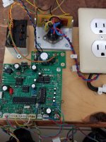
For those interesting in building the AC control attached it is the schematic on how to built the AC power control by ramping the AC on turning the amp ON/OFF. Also the Arduino sketch using for the control of the triac and one photo of my original prototype with a home made SSR relay. l
For those interesting in building the AC control attached it is the schematic on how to built the AC power control by ramping the AC on turning the amp ON/OFF. Also the Arduino sketch using for the control of the triac and one photo of my original prototype with a home made SSR relay. l
Attachments
So you need a PIC to do the work, and you have to program it, besides the other circuitry around it. I will take the simplicity of linear parts anytime I can and digital logic after that.
Hitting a zero crossing is nice but I tried that in the first version of my circuit and it made no difference to the total amount of current at startup. And I don't see a need to ramp down for turn off. Just disconnecting the mains works fine, the bias to the output devices drains the storage capacitors quickly and without thumps or noises, at least in all my amps.
Hitting a zero crossing is nice but I tried that in the first version of my circuit and it made no difference to the total amount of current at startup. And I don't see a need to ramp down for turn off. Just disconnecting the mains works fine, the bias to the output devices drains the storage capacitors quickly and without thumps or noises, at least in all my amps.
If an amp is thumping on power up or power down it has a problem.
Class A amps have an output capacitor so they are a special case.
The worst case I have ever seen was a IRS2092 class d amp.
On power down it would make a siren type noise for a couple of seconds then give an almighty bang through speaker. I had a chat with IR about it and they said the power supply was discharging too slowly. That was my fault as I had used very large smoothing caps.
So I came up with a PIC circuit that monitored VCC and if it fell below about 13 volts it reset the 2092 via an opto coupler. Worked a treat.
I also added a 4 second power up delay.
So is there a tern, other than distortion, where the rail voltages ripple/drop slightly with large lower frequency current draw?
I imagine you could add a regulator to the power supply but with up to 40 output devices current draw would mean a pretty hefty regulator. Maybe just regulate the front end and leave the output on a very stiff supply.
Thanks Jan for the input.
I imagine you could add a regulator to the power supply but with up to 40 output devices current draw would mean a pretty hefty regulator. Maybe just regulate the front end and leave the output on a very stiff supply.
Thanks Jan for the input.
Hi Nigel,
That sounds like an interesting amp, with those noises you would definitely want some control on it.
My amps are Class A up to about 160 watts, the ones I alluded to with the 40 output devices, has an idle bias of 8 amps and even with 760,000uf in the power supply it drains them very quickly and quietly so I haven't seen a need to add your type of circuitry.
So different amps, different requirements.
Have a good one.
I'm thinking of a microcontroller based system, either PIC or Arduino based.
Arduino would make the development and testing really easy and fast, but I think PIC might be better in the long run for the extra simplicity.
For example, even a PIC16F818, or similar can do it easily with hardly anything else around it, but the actual stuff to 1) detect the zero crossing, and 2) do the actual turn-on, with triacs.
This can be made efficient, few devices, just a bit of programming, so it wouldn't require much pcb real estate.
Hey spookydd,
If you have a triac for turn on then you might consider an RC network over it for protection of the triac and a resistor on the gate, again just for protection. And maybe a PI filter at the mains to keep the RF out. A simple project can snowball on you for total parts count. But always fun to see others design ideas. Good luck with it.
If you have a triac for turn on then you might consider an RC network over it for protection of the triac and a resistor on the gate, again just for protection. And maybe a PI filter at the mains to keep the RF out. A simple project can snowball on you for total parts count. But always fun to see others design ideas. Good luck with it.
Hi,
My AC control is using an Arduino UNO.
That makes for a quick and easy development.
How do you actually use the arduino in its "final" implementation? On a pcb.
It's easy, on some UNO versions, to remove the chip from the UNO board, and then plug it in a socket on the final pcb.
So that way the UNO serves as the development tool and programming system, then once the program is verified to work fine, the actual microcontroller can be removed from the UNO board and put on the pcb where it will do its work.
I don't recall at the moment, but the chip must be 18 or 20 pins (the PDIP version), and once programmed, it doesn't actually require all the stuff on the arduino board.
The newer versions are SMT, so that makes popping the chip out not an option.
One good thing about the PIC chips is how they can be programmed in-situ right on the pcb where they'll live. It's not a bad system either.
If you have a triac for turn on then you might consider an RC network over it for protection of the triac and a resistor on the gate, again just for protection. And maybe a PI filter at the mains to keep the RF out. A simple project can snowball on you for total parts count. But always fun to see others design ideas. Good luck with it.
Of course, but that's not really that different from other methods. And I don't think the part count increases that much just because triacs are used.
My ultimate goal is making a centralized power up command system that will sequentially power up several toroids for several power amps. And along the way, using this existing micro-controller, it's doable to add fairly simply a muting command system.
I would sequentially power up each toroid, and only then, once all of them are up and running, would I also sequentially un-mute each power amp.
Stupid me! I didn't even recall there are optocouplers that have the zero crossing detect feature right inside them, so there is no need for an extra zero crossing sensing and programming to react to it. It can be done very simply without even thinking about the zero crossing, because the optocouplers do it transparently.
All the better. Lower part count. Simpler. No need for extra development effort. Less pcb real estate...
So I can concentrate on using the micro-controller to sequentially trigger each coupler, to power up each toroid one at a time, and then un-mute each power amp afterwards, sequentially! That's the way to go...
Hi,
It is does not matter if the opto coupler have a zero crossing or not and fire the traic at the zero crossing. With that you are not doing anything different than using a switch. What do you want it is slowly ramp the AC up and slowly ramp it down. It is like a light bulb dimmer. You use the micro to fire the triac at the right time of the AC fase angle.
It is does not matter if the opto coupler have a zero crossing or not and fire the traic at the zero crossing. With that you are not doing anything different than using a switch. What do you want it is slowly ramp the AC up and slowly ramp it down. It is like a light bulb dimmer. You use the micro to fire the triac at the right time of the AC fase angle.
Hi Nigel,
That sounds like an interesting amp, with those noises you would definitely want some control on it.
My amps are Class A up to about 160 watts, the ones I alluded to with the 40 output devices, has an idle bias of 8 amps and even with 760,000uf in the power supply it drains them very quickly and quietly so I haven't seen a need to add your type of circuitry.
So different amps, different requirements.
Have a good one.
Class A is usually protected by an output capacitor so DC detect isn't much use.
I have found DC protect vital for my amplifier designing. Its easy to miss a solder connection when soldering and then get full rail volts on output.
I must have saved a fortune in speakers over the years.
I also did a soft start circuit using a triac.
It slowly ramps up phase angle until full mains is applied.
Means you can use a better fuse as there isn't quite the same initial surge of current.
The main goal of the soft start is pretty much only to tame that huge inrush current, and so firing up a toroid as close as possible to zero crossing does just that, and it's enough.
There is no need to ramp it up slowly if the bulk of the inrush has been dealt with.
There will be some inrush, still, due to the charging of the cap banks downstream, but nothing like that one from the toroid itself. The spike won't be as large if zero crossing was used.
There is no need to ramp it up slowly if the bulk of the inrush has been dealt with.
There will be some inrush, still, due to the charging of the cap banks downstream, but nothing like that one from the toroid itself. The spike won't be as large if zero crossing was used.
- Home
- Amplifiers
- Power Supplies
- Yet Another Soft Start Circuit