Hi @tauro0221, thank you very much for the diagram in #104. It occurs to me that the hardware/software which sets the triac firing time (thus the phase angle), can be prototyped, tested, debugged, and validated using a low voltage AC sinewave. Perhaps such as the output of a mains-to-12.6VAC stepdown transformer. Now you can connect meters and scope probes and even fingertips to the apparatus, without high voltage danger. You can also attach an earth ground, which is a safe and handy reference for the test gear.
After everything is working beautifully and producing the exact oscilloscope displays you desire, only then do you install the (proven!) circuitry into a PCB which uses the live AC mains. Very nice.
After everything is working beautifully and producing the exact oscilloscope displays you desire, only then do you install the (proven!) circuitry into a PCB which uses the live AC mains. Very nice.
Hi,
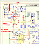
Normally used a small wall AC transformer to feed the Arduino and also use it to get the zero crossing pulses to fire the traic. You need a full rectifier to get the pulses for the neg/pos side of the AC. I fired the traic on both pos/neg of the zero crossing of the AC to get smooth voltage at the secondary. Also if you do no want to use the transformer option you can get an opto coupler to get the zero crossing pulses no matter if your input AC voltage it is 120/220 AC volts. The one you can us it is the H11AA1 it will give you a pulse in the neg/pos of the AC. It is a simple concept to eliminate inrush current. Maybe people do not see the concept that what you doing it is slowly controlling the incoming voltage from a low to high voltage feeding the primary and at the same time you controlling the secondary output voltage. It is like you use an auto transformer to vary the input voltage of a transformer. The schematic it is in the #26 of this thread. Like I said before been using this concept for almost 6 years with no problems. Also you can control the voltage ramp by triggering the triac few times at the same angle of the AC.
Normally used a small wall AC transformer to feed the Arduino and also use it to get the zero crossing pulses to fire the traic. You need a full rectifier to get the pulses for the neg/pos side of the AC. I fired the traic on both pos/neg of the zero crossing of the AC to get smooth voltage at the secondary. Also if you do no want to use the transformer option you can get an opto coupler to get the zero crossing pulses no matter if your input AC voltage it is 120/220 AC volts. The one you can us it is the H11AA1 it will give you a pulse in the neg/pos of the AC. It is a simple concept to eliminate inrush current. Maybe people do not see the concept that what you doing it is slowly controlling the incoming voltage from a low to high voltage feeding the primary and at the same time you controlling the secondary output voltage. It is like you use an auto transformer to vary the input voltage of a transformer. The schematic it is in the #26 of this thread. Like I said before been using this concept for almost 6 years with no problems. Also you can control the voltage ramp by triggering the triac few times at the same angle of the AC.
It is a simple concept to eliminate inrush current.
True. It would be nice with a measurement to verify that it did indeed eliminate the inrush current, though.
Tom
... Like I said before been using this concept [triac + uC for phase angle control] for almost 6 years with no problems.
Bryston has been using it for ten years: from March 2010 to today. No reported problems that google is able to find.
_
Attachments
Hi,
To:tomchr I remembered reading it with a hook on type current meter without the micro the reading on powering the amplifier up was about 1 to 3 amps and when using the micro was unnoticeable but do not know if it was because the range of the meter. My advice it is that a member of this thread built one and report back the results. It is simple to built.
To:tomchr I remembered reading it with a hook on type current meter without the micro the reading on powering the amplifier up was about 1 to 3 amps and when using the micro was unnoticeable but do not know if it was because the range of the meter. My advice it is that a member of this thread built one and report back the results. It is simple to built.
1-3 A sounds way optimistic for a large power transformer.
Anyway. I was asking because I hoped you maybe had an oscilloscope shot of the current before/after. That does not appear to be the case. That's fine. The circuit should work. I'm just curious about how well it works. I would also be curious about whether there would be different optima for the turn-on phase angle for resistive loads vs various types of reactive loads.
Maybe I'll get curious enough that I go build it (and brush up on my uC programming skills in the process.)
Anyway. Thanks for planting the thought in my head.
Tom
Hi,
I also include the arduino sketch in the thread #26 so you can test it and report back. Maybe you can improve the programming since I am not an expert programming. As long it is working do not see any problem. I still have the original prototype and would see if can do some current scope. Belief me you would regret building it.
I also include the arduino sketch in the thread #26 so you can test it and report back. Maybe you can improve the programming since I am not an expert programming. As long it is working do not see any problem. I still have the original prototype and would see if can do some current scope. Belief me you would regret building it.
Hi,
For you information attached it is a timing drawing showing how I control the firing of the triac to ramp the AC as it is done when powering an amplifier ON/OFF. The triggering of the traic it is done using the zero crossing as a sync to fire the triac on. As shown in the drawing the firing of the triac start at 90 degree and it is fired in both side in the positive side and in the negative side of the sine wave and moving the firing pulses that trigger the triac toward the 45 degree of the sine wave. At 45 degree the triac it is turn on full time.This also it is done in reverse when powering the amplifier off. Also if you want to slow down the ramp them your fire the traic 3 to 6 times at the same angle. I used in my system 3 times. In other word your are slowly ramping the AC to prevent the inrush current at the same time slowly charging the capacitors in the secondary side. The more you firing the traic at the same time the slowly it is the ramp. Hoped this clarified and have an idea how using a micro and the zero crossing the ramping of the AC can easily be done. As you can see your are using the micro in the same way you are using a dimmer to control a light bulb or to control the speed of a fan. I have been using this method for almost 6 years without one single problem or break dwon.
This is something what I have thought before but the solution seems universal to me as it just works like dimmer stat way to starting.
Did u had any issues in noise while starting? on the speaker outs or the load on the triac thermally or any reactive problems as its driving heavy inductive load?
Hi,
I do not have any noise problems because I am using at a home built LM3886 amplifier that all the amplifier functions are controlling by the micro. The first thing it is ramp the AC once it is Up it will check the PS voltage if found OKAY then proceed to ramp the rails voltage and from here the rails voltage are control/regulated to 38 volts by the micro. After the start up it is completed the micro monitoring the speaker current / the LM3886 temperature heat sink. and the rails voltages. If any of the speaker channels current it is high the micro will immediately shutdown the rails voltage. Also the micro constantly monitor the speaker current/voltage and the temperature and display it in a LCD display.
Now I tested the start alone box in a Dynaco 120 and did not notice any noise in the speaker. At the begging noticed small noise coming from the speaker but noticed that the traic bypass relay was not kicking in. By tapping the relay it started working right and did not notice any noise coming from the amplifier. The stand alone box it is been in storage for about 6 years. As I mentioning before the triac it is bypass because it will be firing on every time that goes thru the zero crossing. This will caused some small electromagnetic noise. The triac job it is just to ramp the AC and once it is completed the triac will no longer needed. Hoped this will answered must of the questions and doubt you may have. It is possible that it may need some more noise testing.
Great then you were using one PIC ucontroller for the entire job of monitoring and also the softstart application I guess.
I just have two questions one is does this radiates EMI? either conductive or Emission radiation just for CE compliance scenario?
secondly what was the largest transformer and cap bank combo you have tested this with? What is the peak inrush current observed when you have used this.
The above two inputs will conclude lots of things.
Hi,
About the EMI do have any equipment to test it. Now remember the ramp it is for a short period of time and like a said before the triac it is bypass once it is bypass the transformer will run like in a normal operation and the triac have built in EMI suppression. Right now my LM3886 it is a toroidal transformer and the Dynaco it is an EI transformer. I think that the size of the transformer depend of the size of the triac. The one I am using can handle 20 amps 220 volts AC non zero crossing since I am controlling the zero crossing with the micro. Sorry, if am misleading since this project was done 6 years ago and at my today age just remember one week after one week it is gone.
About the EMI do have any equipment to test it. Now remember the ramp it is for a short period of time and like a said before the triac it is bypass once it is bypass the transformer will run like in a normal operation and the triac have built in EMI suppression. Right now my LM3886 it is a toroidal transformer and the Dynaco it is an EI transformer. I think that the size of the transformer depend of the size of the triac. The one I am using can handle 20 amps 220 volts AC non zero crossing since I am controlling the zero crossing with the micro. Sorry, if am misleading since this project was done 6 years ago and at my today age just remember one week after one week it is gone.
Hi,
I have a suggestion if you want to use a big transformer just built the controller and just use the transformer with the capacitors bank and do the test to see how it will handle the AC ramp. From the results them decide to see if you want to use it or not. Simple. I am not using a PIC micro it is a ATmega328P chip and programming it with the arduino IDE.
I have a suggestion if you want to use a big transformer just built the controller and just use the transformer with the capacitors bank and do the test to see how it will handle the AC ramp. From the results them decide to see if you want to use it or not. Simple. I am not using a PIC micro it is a ATmega328P chip and programming it with the arduino IDE.
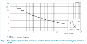
I think you'll be just fine if your triac's "IT(RMS)" datasheet specification, which is the maximum rated continuous current, is significantly higher than your transformer's max continuous primary current. In practice, this makes us very confident that the triac's "Non repetitive peak on-state current" will be waaaaaay higher than the soft start protected inrush.
So, for example, if your transformer is rated at 1000 VA and if you live where the mains voltage is 115V RMS, then
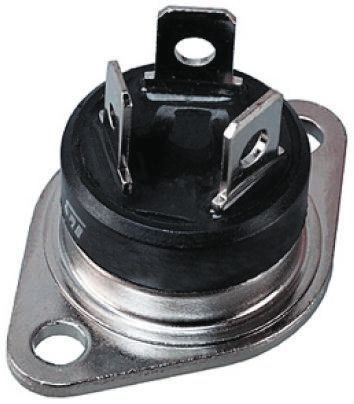
So if you choose the $0.87 BT139 triac (datasheet), whose "IT(RMS)" specification is 16 amperes, you'll be fine, since 16 amps is much greater than 8.7 amps. The BT139's Non repetitive peak on-state current is shown in datasheet Figure 4, reproduced below. It certainly has plenty of safety margin for a soft start protected inrush.
_
- Max continuous primary current = (transformer VA rating) / (mains RMS voltage)
So, for example, if your transformer is rated at 1000 VA and if you live where the mains voltage is 115V RMS, then
- Max continuous primary current = 1000 / 115 = 8.7 amperes
So if you choose the $0.87 BT139 triac (datasheet), whose "IT(RMS)" specification is 16 amperes, you'll be fine, since 16 amps is much greater than 8.7 amps. The BT139's Non repetitive peak on-state current is shown in datasheet Figure 4, reproduced below. It certainly has plenty of safety margin for a soft start protected inrush.
_
Attachments
I think you'll be just fine if your triac's "IT(RMS)" datasheet specification, which is the maximum rated continuous current, is significantly higher than your transformer's max continuous primary current. In practice, this makes us very confident that the triac's "Non repetitive peak on-state current" will be waaaaaay higher than the soft start protected inrush.
- Max continuous primary current = (transformer VA rating) / (mains RMS voltage)
So, for example, if your transformer is rated at 1000 VA and if you live where the mains voltage is 115V RMS, then
- Max continuous primary current = 1000 / 115 = 8.7 amperes
So if you choose the $0.87 BT139 triac (datasheet), whose "IT(RMS)" specification is 16 amperes, you'll be fine, since 16 amps is much greater than 8.7 amps. The BT139's Non repetitive peak on-state current is shown in datasheet Figure 4, reproduced below. It certainly has plenty of safety margin for a soft start protected inrush.
_
But eventually its better to trigger at zero crossing detection and then turn on the large triac instead of random phase triac isnt it?
Consider the OP`s thought of using two 10ohm NTC for 230V will limit the inrush as his spec as 12Amps and with zero crossing even the cap bank in the secondary will get benefited with NTCs infirst place rather than just having large heatsinked resistors. Im thinking this way.
There is a soft start working scheme, you can collect it yourself or buy.
AIYIMA 1000W Power Supply Delay Power Soft Start Protection Board High Power For Class A Amplifier DIY 30A Relay Protection 220V-in Amplifier from Consumer Electronics on Aliexpress.com | Alibaba Group
That looks interesting and what is the Value of C01 is it X2 capacitor?
But eventually its better to trigger at zero crossing detection and then turn on the large triac instead of random phase triac isnt it?
Consider the OP`s thought of using two 10ohm NTC for 230V will limit the inrush as his spec as 12Amps and with zero crossing even the cap bank in the secondary will get benefited with NTCs infirst place rather than just having large heatsinked resistors. Im thinking this way.
Remember that turning on at zero crossing won't cause the lowest inrush current, but pretty much close to maximum. The zero crossing can be used as the "reference" point from which to act, but the action of turning on should be out of phase with zero crossing, and it's better to do this progressively, with shifting the phase..
That looks interesting and what is the Value of C01 is it X2 capacitor?
Doesn't look like a very "modern" way to do things. With electromechanical relays? And 3 of them!!!! Bulky thing and not at the peak of technology for sure.
Try out your ideas on the lab bench! You'll learn a lot and you'll have a bunch of fun. Tom Christiansen has a white paper on his Neurochrome site showing how to MacGyver a decent-performing current sensor (probe) for your oscilloscope, while spending less than fifteen dollars. Mains current waveforms on your oscilloscope! Measured data rather than opinions! You will be thrilled, it will be glorious.

Thanking for the input Mark. I have a question that what is that when the inrush is max at zero crossing point then what is the use of Triac in the OP circuit. It doesnt have zero crossing detection as well and also I found out in neurochrome website that inrush is max at voltage zero crossing.
https://cdn.shopify.com/s/files/1/0...tron_1kVA_820Rload-Annotated.png?v=1593376482
what if we use a choke to shift the phase and then use the zero crossing triggering?
https://cdn.shopify.com/s/files/1/0...tron_1kVA_820Rload-Annotated.png?v=1593376482
what if we use a choke to shift the phase and then use the zero crossing triggering?
- Home
- Amplifiers
- Power Supplies
- Yet Another Soft Start Circuit