Hi And thanks for reading this thread.
What do you think of adding polypropylene film caps to an amplifier's power supply in an effort to improve sound quality. Do you think there will be any improvements?
I have a quad 405, am thinking of replacing the old 10 kuf caps in the power supply, also paralling in a 100uf poly and a 10 uf poly across. There are already 0.1uf polys on the amp boards.
Thanks
Short answer: NOadding polypropylene film caps to an amplifier's power supply in an effort to improve sound quality. Do you think there will be any improvements?
or not audible at least (and very very difficult to even measure, go figure)
You are talking serious money and bulk here and very much doubt you will hear any improvement.I have a quad 405, am thinking of replacing the old 10 kuf caps in the power supply, also paralling in a 100uf poly and a 10 uf poly across. There are already 0.1uf polys on the amp boards.
Better spent in replacing "old 10 kuf caps" with modern ones ... which to boot will be better because of continuous production improvements.
Will they soun d better?
Well, they will have more influence on sound than earlier add ons, that´s for sure.
Last edited:
It is rare for cap bypassing to do any good. Mostly it does no harm, but is simply a waste of time and money. Sometimes it causes problems, which may or may not be audible.
It is popular because it is easy to do and the people who promote it know just enough about electronics to confuse themselves and others.
It is popular because it is easy to do and the people who promote it know just enough about electronics to confuse themselves and others.
No, not the slightest, its not on the signal path.Hi And thanks for reading this thread.
What do you think of adding polypropylene film caps to an amplifier's power supply in an effort to improve sound quality. Do you think there will be any improvements?
"10 kuf" do you perhaps mean 10mF (milli farad)? 'f' means femto, 'F' means farad. Prefix letters do not stack in SI.I have a quad 405, am thinking of replacing the old 10 kuf caps in the power supply, also paralling in a 100uf poly and a 10 uf poly across. There are already 0.1uf polys on the amp boards.
Thanks
There's no harm adding extra capacitors across the large filter caps, it will improve high frequency performance somewhat, but in reality its the caps on the amp boards that matter for high frequency performance as they are not separated from the load by lots of stray inductance.
100µF polyproplyene is not warranted though, 10µF + 0.1µF ceramic will be much better for high frequencies. Wound film caps are typically much more inductive compared to ceramic multilayer.
If you can find datasheets, look for the self-resonant frequency of the capacitor, that is the really useful info.
At the reservoir cap is the wrong place to put any small , low-esr 'bypass' capacitor - these belong ONLY to bypass the target load HF current demands (i.e. to keep current loops as small as possible) - and therefore only when you know & can measure why you want such a thing.
[You see such things casually on many DIY regulator PSU pcb ideas - there's almost always a film/ceramic 0.1uF or sim placed across the output of the regulator. It's entirely the wrong thing to do - for several reasons - and never helps. ]
[You see such things casually on many DIY regulator PSU pcb ideas - there's almost always a film/ceramic 0.1uF or sim placed across the output of the regulator. It's entirely the wrong thing to do - for several reasons - and never helps. ]
Thanks.
Most do not like the idea of film caps across the power supply caps.
What do you think of film caps across the amp board components. I can see 4 places where they may be of potential benefit. Across the power supply to the op-amp, power supply to the driver transistors, power supply to the output transistors, and at the point where the cables from the mains power supply are soldered onto the amp board there is already a 0.1uf at this point. What value do you think if film caps may be warranted.
Alternatively i have 2000uf panasonic electrolytic caps which could be soldered at the 4 places mentioned above. Being of large value these panasonics could act as a local power supply for the components to tap into rather than having to wait for the mains power supply to catch up. So would have a different function than the film caps which would have more of a smoothing function.
Which do you think is the better way to go.
What do you think
What is you purpose in this endeavour? To improve the sound, or to appease some engineering God?
If it relates to the sound there is only one way: try and see if you can hear an improvement and if the spot where you add them is audible.
If you can hear no change and especially if the change is not an improvement does it make a difference what anyone else thinks? Would you still do it?
Thanks!
phase: I have done some reading but can only find posts about people putting small 0.1 uf caps across the power supply, nothing about big 100uf or 10uf film caps. Also i can find no comparison of using big electrolytics vs film caps, the question i asked earlier, using big electrolytics as reservoir caps compared to smaller film caps which may serve as more a smoothing function on the amp board.
DF96: Why do you say that, there are many people who have replaced the old 70's caps in the amp power supply with modern day low esr caps and reported big improvements, i would have thought that polys with even lower esr should make a difference.
Mark Tillotson: Why do you say 100uf are unwarrented, that 10 and 0.1 are better for higher frequencies. Are you saying the smaller the cap the higher the frequency it affects? If so the 100uf may go low enough to affect the midrange. Why do you say ceramics, i thought they gave a screeching kind of sound.
sfleming:What value(s) solens did you use, can you please expand on " sounded better " in what way, what do you observe. I do have plenty of space because another mod that i did is to replace the transformer with an external one on a fly lead so there is plenty of space where the old transformer used to go
analog_sa: Thats not really answering the question. There are a lot of people who replace caps but not quite in the manner that i am doing, just trying to find someone who may have done this already and is willing to share
sq225917: what value would you suggest
martin clark: what do you think of the 4 places i have mentioned, are you in favour of a small film or a large electrolytic at these points.
merlin: can you please share your experience of the auricap.
I agree with previous - it isn't just a "without them" problem. I am 99% sure it is design (construction) problem and so on.
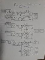
Almost all my designs are "without them" - I prefer to use RC-snubbers in rectifiers instead of, and I haven't had such a problem.
So, such a soldering iron is a good multi-functional unit to perform reliability and general design tests, so keep it and use widely.")
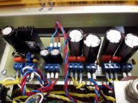
Here is an example of one of my rectifier boards (for soviet Г3-118 low-distortion generator):
You can see orange 0.560 uF x 63V film caps, but they are at the input of rectifiers. And there are SMD-resistors under the circuit board connected in series with them.

Almost all my designs are "without them" - I prefer to use RC-snubbers in rectifiers instead of, and I haven't had such a problem.
So, such a soldering iron is a good multi-functional unit to perform reliability and general design tests, so keep it and use widely.
Here is an example of one of my rectifier boards (for soviet Г3-118 low-distortion generator):
You can see orange 0.560 uF x 63V film caps, but they are at the input of rectifiers. And there are SMD-resistors under the circuit board connected in series with them.
Attachments
Last edited:
- Status
- This old topic is closed. If you want to reopen this topic, contact a moderator using the "Report Post" button.
- Home
- Amplifiers
- Power Supplies
- Adding film caps to psu, any good