"For different brand LEDs the temperature coefficient of the forward voltage can vary between –1 and –20 mV/◦C":
http://web.vu.lt/tmi/a.zabiliute/wp.../2/2013/11/LED_Temperature_characterstics.pdf
With the particular LEDS bar and having the LM334 intentionally located at a closer distance to the main radiator there is an acceptable Vout negative drift overall for my purposes. Few tens of mV usually.
BTW the 51R should not connect to the Vref node but to the input DC rail in your simulation.
With the particular LEDS bar and having the LM334 intentionally located at a closer distance to the main radiator there is an acceptable Vout negative drift overall for my purposes. Few tens of mV usually.
Yupp, this is just a bit of an academic exercise -- design with two LED's, with two cathode to cathode zeners, and a simple resistor. (Correction you pointed out made!)
Attachments
Here's a practical exercise:
Stick a thermocouple next to the LEDs bar, load the thing, circle above with a hot air gun across the main sink over to the bar. Output semis & Vref stuff reside there. Take it from 28C to 65C, stop. Went down to 40C because it took time to react. Snap pics as in before and after second-rate marketing adverts. Oops... better than expected")
Stick a thermocouple next to the LEDs bar, load the thing, circle above with a hot air gun across the main sink over to the bar. Output semis & Vref stuff reside there. Take it from 28C to 65C, stop. Went down to 40C because it took time to react. Snap pics as in before and after second-rate marketing adverts. Oops... better than expected
Attachments
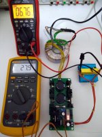
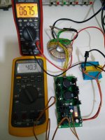
I finally managed to sort-of complete my build of the prototype board Salas was kind enough to provide. Compared to Nikos' other (shunt) power supplies, this power supply is by far the easiest one to build. Pretty much anyone with a soldering iron should be able to build it. No matching or measuring of parts is required and it is very hard to put the wrong part in the wrong place. Just make sure that the LED bar gets soldered on with the correct orientation. For the moment I'm powering my unit with my lab power supply, while I'm deciding where to test it first. Having set it up for 5.1V output with no load (3 LEDs lit), the output will drop only by 30mV when having to output ~280mA. Very nice. The reg itself with no load will burn about 11mA. For the moment I have it powering an RPi 3 with no peripherals, which draws about 265mA at idle.
.jpg")
.jpg")
The rectifier diodes that I put in (MUR810G, no heat sinks) don't even get warm to the touch. Same goes for the output transistor's heat sink (input voltage is about 12VDC). Next up is soldering-on a couple of filtering capacitors and connecting an actual transformer. I plan on testing it on my RPi3, my SBT and probably on something more demanding like a NAS box.
The rectifier diodes that I put in (MUR810G, no heat sinks) don't even get warm to the touch. Same goes for the output transistor's heat sink (input voltage is about 12VDC). Next up is soldering-on a couple of filtering capacitors and connecting an actual transformer. I plan on testing it on my RPi3, my SBT and probably on something more demanding like a NAS box.
Very nice so far. The moment you load it, the pass transistor conducts current and increases Vbe a little. That little gets deducted from Vout. Thus no over-voltage reaction. Such behavior is benign for feeding digital gear. There's no control loop to run compensate the loss and overshoot.
When you want to know its dynamic output resistance, make a move from say 2A to 3A load and compare Vout before output cabling. You should find about 0.02Ω dynamic resistance.
Also, in open plan placement like it is operating now, you will probably find 30-40mV upward thermal drift after 5 minutes and not a 10mV drop as in my example with hot air blasting. That one was for imitating a closed box rising ambient.
When in open plan, the LEDS are far enough from the board level sink to be much affected, and they will not contribute as much negative mV settling drift. So the closer located CCS chip's positive current drift dominates yet a little and feeds them bit more current pushing up their mV VF more than they compensate by their natural thermal mV VF loss.
In any case you should not find wide enough Vout drift differences from cold boot to hot loaded and back again that may worry you. But test to confirm.
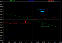
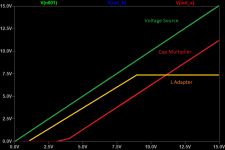
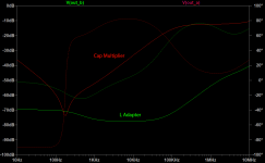
The output voltage of the L-Adapter would appear to be stable with respect to line voltage. The cap multiplier output voltage is directly related to line voltage.
Maybe a picture or two help. Making cap values equal, the L-Adapter has superior PSRR and pretty decent regulation. The cap multiplier (a generic here using NMOS) has decent PSRR but the output tracks the input once the loss across the FET is taken into account:
Maybe a picture or two help. Making cap values equal, the L-Adapter has superior PSRR and pretty decent regulation. The cap multiplier (a generic here using NMOS) has decent PSRR but the output tracks the input once the loss across the FET is taken into account:
Attachments
I don't know the USB RT spec, but I have tested the RPi3 and a 12V Win 10 mini-PC on this PSU without any issues. They both booted fine and held fine even when pressed for CPU usage % on multimedia streaming without freezes or resets. I many times pushed them to stuttering and they would always recover.
Had couple of days with actual testing. L-adapter works really nice. I have 12v transformer and the adapter delivers 6.3v to heat up a pair of 6sn7 in the aikido preamp. It takes about 10-15 sec to go from 6.18v to 6.25v and then drift slowly to 6.29 while fully warming up. Of course all those measured not with a scope but with a regular multimeter, so mind the accuracy. I have 2.5” heat sinks in the transistor and it is a little bit to warm for my taste, 70-74 C depending on my room temp. I guess 12v input voltage contributed to that. Will look for bigger sink and will go to a 9v transformer in future. Diodes are barely warm, but I still installed them in the sinks.
Sound... well hard to say as I did not do A/B, but there is less hiss on idle from the tweeters than with PS-21 psu.
And yes, one oh these days I will stop soldering and will start making proper enclosures

Sound... well hard to say as I did not do A/B, but there is less hiss on idle from the tweeters than with PS-21 psu.
And yes, one oh these days I will stop soldering and will start making proper enclosures

That measurement across D11 is Vin-Vout so 7.5V*1.2A=9W dissipation on each board level sink.
Because heaters are a constant load, no breathing intervals.
The start up & warm up +0.11V dif total is still ok for room to 74C on sinks by the way. That's a high delta temp.
Nice, the practical counterbalancing of the elements works well enough. For such a simple Vref I mean.
When setting it unloaded allow for those 15 secs of initial settling. It's due to the CCS chip coming up.
But that's high temp on sinks to go nicely in a build anyway.
Half that voltage drop would be fine for the psu to work properly. 9VAC Tx should do that.
But always check loaded results and accept no less than 2.5VDC drop across D11.
Meantime, do you have a hefty metal plate to mount the main transistors on it instead? Silpads for insulation also?
I think I will order 9V transformer. AS-0509 - 50VA 9V Transformer - AnTek Products Corp this should work. Yes I will for sure think of mounting it on a big metal plate and a chassis. whenever I have one. BTW PS-21 regulator LD1085 with same 2.5 heatsink is even hotter 80+ C.
Yes I will for sure think of mounting it on a big metal plate and a chassis. whenever I have one.
Wait to see where the 9V Tx will drop the sinks temp first. Maybe around 50C in a 20C room with your parameters.
Me and a friend of mine took an afternoon off to test the following PSUs with an ADI-2 DAC from RME:
the original SMPS, L-adapter and Salas BIB. This time the differences were easily spotted: SMPS gave a tube-like sound, very musical and relaxed. When compared with L-adapter it was obvious that there was a slight roll-off in high frequencies (SMPS), less details and not so quiet background. L-adapter apparently was more dynamic, neutral in character and had more extend especially in the high frequencies.
Finally we put BIB in the test (previously we did another test which was very quick because BIB was overheating). With a huge heatsink BIB (RME needed over 1.5A at startup) had the dynamics but also was very musical without loosing details. My friend preferred BIB but was troubled by the size of this psu.
L-adapter voltage sunk only 6-7 mV with load, very stable during playback.
Next test with a computer, hopefully this week
Nice feedback. Thanks for posting such info. The technically excellent RME DAC is supposed to be indifferent for external PSU quality, but not down to all the SQ details after all.
When we did the first test with BIB, we then also concluded that it was more musical than the SMPS one but was not that obvious (we have to listen carefully to spot the differences) and was not worth the hassle (at least I wouldn't bothered). With no overheating problems, having more time listening to it, now I would say that the other PSUs didn't change the character of the DAC (the upfront, not much depth presentation of it) but they had impact on many characteristics that make a device pleasing or not.
I do like harmonic-rich sound but I don't like the presentation of this DAC and L-apapter / BIB made it at least listenable.
The change to a more 'meatier' sound I described for L-adapter powering Bufallo 9028 wasn't heard this time most probably because ADI2 already has that sound so it's there in all PSUs
I think the main use for L-adapter is for heavier, not stable, loads so I'm gonna focus in powering such devices (Tinker, PC)
- Home
- Amplifiers
- Power Supplies
- L-Adapter