I'll put in a 5A slow blow and try againTo properly fuse a 300VA 120VAC mains transformer it takes a 5A slow blow on its primary side. To withstand its momentary magnetic buildup inrush.
There's substantial reservoir capacitance on the L-Adapter pulling charge up inrush current for a little bit longer too.
26VAC secondary maybe too plenty for 19VDC 3.5A reg out. Can add some unnecessary Q2 dissipation. See how much raw DC is made across the reservoir caps and if they are well rated for it.
Why you only saw 7V+ initial DC output I am not sure since you didn't find something obvious in the rest of the circuit yet. Try set J8. Check if healthy Vbe on the driver and pass transistors first and also see not to have oriented any caps or the diode (D11) wrong. R3's value should be checked too.
I checked and the secondary is 24 VAC and what I measured was unloaded. But I agree that may be too high. I will switch the transformer to 22 VAC secondary. Is the 300 VA too high for 3.5A DC?
This is similar to what I'm doing. I'm using it to power a mini STX SFF build. Thanks for the pointer. I will try with no jumper and adjust VR1.@sbelyo
I have built and run an L-adapter to output 19.5 volt to a thin-client...It works fine for more than 2 years now.
No jumper used. VR1 adjusted to give 19.5 out
Build here...
L-Adapter
24VAC unloaded is more manageable than 26VAC and you may try with that for now. If loading and sink temp are happy keep it. Transformers nominal is a bit all over the place for various reasons, there are 22VAC that could give 24VAC unloaded and so on. 150VA-200VA would also work without much strain for 70W DC (20V*3.5A) and 300VA will run coolest.
There is not a too much VA problem when you already have it. Except if creating a transformer size fitting problem in a given enclosure. Electrically its just like using a higher power resistor than the lowest rated.
What you want is good (>2.5V) DCraw-DCout margin after ripple deduction at peak load consumption. What a DC meter shows is always after ripple.
*There is a paragraph in the instructions PDF talking minimum transformer requirements for various DC output voltage levels.
Thank you sir!
I realized C3 and C4 are only 35V so I ordered 50V versions and will swap them out on Saturday. I also ordered another set of components just in case I damaged something. My guess is those 35V caps saw 37V for a minute or two. Not sure if they're toast or not but replacements are on the way. Even if I switched to a lower voltage secondary (22V) they would be right at the limit.
I realized C3 and C4 are only 35V so I ordered 50V versions and will swap them out on Saturday. I also ordered another set of components just in case I damaged something. My guess is those 35V caps saw 37V for a minute or two. Not sure if they're toast or not but replacements are on the way. Even if I switched to a lower voltage secondary (22V) they would be right at the limit.
You know, there are silicon losses increasing with current, and there is AC ripple riding on DC increasing and eating some of it too, so its more practical to measure what DC levels you get at various points in your own application before becoming a theory expert. You want to strike a balance between enough but not excessive DC voltages for manageable Q2 dissipation sinking temperatures, still with ease of load drive. A certain load of your interest.
Hobbyists usually don't look to calculate the most economical configuration in size and cost but there is no reason to be hugely wasteful either.
A concise Hammond link about what to know on various rectification schemes: Design Guide For Rectifier Use - Hammond Mfg.
Hobbyists usually don't look to calculate the most economical configuration in size and cost but there is no reason to be hugely wasteful either.
A concise Hammond link about what to know on various rectification schemes: Design Guide For Rectifier Use - Hammond Mfg.
A nice thing to consider is synchronous rectification with LT4320, especially at applications high current draw.
Sonic results are also great. My RPI4 currently is powered with LT4320, low Rds MOSFETS and L-Adapter. This combination was the best I had soundwise. I guess Salas SSLV1.3 UltraBiB would be even better, but I'd never go this path since the enormous heatsinks required!
PS: My SS amp (a daTZeel Frankenstein clone) is also powered with four LT4320
I am getting 0.6v difference from min to max of the trimer and 1,75v jump from jumper to jumper.
So with 0.6v in adjusting the trimmer I can not get to 5,3 volts (without load)
in order to get somthing more than 5,1 for 3Amp load that I would like (I get 4,8 and the device does not boot) .
I get a gap fron 5.12 to 6.20 (without load)
Is there any chance that I'm using the wrong type of VR1 trimmer?
I buildup the full kit and I didn't check if the trimmer was of the correct spec, or can there be any other mistake?
I am getting 0.6v difference from min to max of the trimer and 1,75v jump from jumper to jumper.
VR1 should be 500 Ohm and IC1 giving about 5mA constant current when R2 is 12R. Those conditions normally give 2.5V VR1 range adjustment. Something's probably wrong with a value and/or parts orientations. Is there enough transformer for the job resulting to 2.5V or more DC across D11? You can measure the trimmer's set value, end to end pins, as it sits on the board. Has no capacitor right across it so to fool the Ohm meter.

Yes, confused when assembling at the first place, had them measured but...
Thanks for the support!
Initial impressions when listening at Lindemann's Limetree Network player in comparison to the original smps where that voices in classic blues and electronic where more free and real without this "shadow" that exists in digital, much more speed all over, lows much more intense and clean. Things where improved when changed the power black cable with an Acoustic Revive branded, so there are more things that can give better sound.
Now I think I'll have to try an ultraBib in order to make things even better.
Thanks for everything.
You are welcome. Nice that you like it. L-Adapter is suitable in many ways for that kind of gear.
I visited: Lindemann Limetree Network II
"For the power supply we use a high-quality “medical grade“ wall plug transformer which ensures a particularly good isolation from line disturbances. Owing to the elaborated onboard filtering and special voltage regulators, we were able to realize an exceptionally low-noise power supply with a ripple voltage below 10 µV."
Yeah, right. You shouldn't have heard a difference with L-Adapter if so. An amount of switching noise still creeping in somehow it seems.
Limetree specifies Power supply: 5 V DC
Power consumption: 0.1 W standby, 3.5 W operation, max. 12 W
So there is quite a min to max span to anticipate in a constant current biased shunt reg like uBib when the network player is either on standby or when operating. Its like using a 12W Class A amp at 0.1W-3.5W most of the time. Nearly all of the power on tap going to its sinks during that time. There is also the CCS Mosfet circuit with 5V across it in a uBib so double that waste.
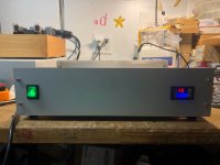
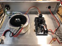
I reduced the VA to 200 and used a 3.25A Slow Blow fuse.5A slow blow trafo primary fuse in the end? What is the capacitance of those Epcos? Nice touch the front panel meter.
The caps are 6800uf 35V
I probably should've used 10,000uf I have some just is case it's an issue. I just didn't want to desolder them.
- Home
- Amplifiers
- Power Supplies
- L-Adapter