Second case is borderline. Dependent on the transformer's regulation percentage and load current asked. You should check if at least 2.5V DC remains across the D11 diode when on the actual application.
Thanks, Salas. Current draw will be around 450ma so not a lot. Will definitely check the DC voltage across the diode on load just to check its stable
You should choose a slow blow primary side fuse based on your transformer's VA rating. That's not to be blowing the fuse by the transformer's inrush current capability at turn on. Primary current is less than secondary current in a step down transformer.
What is your VA? For 230-240V primary and 50VA use around 600mA slow blow. For 100VA around 1.25A.
What is your VA? For 230-240V primary and 50VA use around 600mA slow blow. For 100VA around 1.25A.
I just bought a few boards and mini kits from TeaBag. I am looking at building in total 4 psu's. I will start with a 12V version for a RME ADI2 DAC.
Looking at the transformers I see that most have 2 secondaries. Now i found a 100VA toroid with a single 14.5V secondary and 6.9A. I think this would be perfect for a 12V L-adapter.
I am also looking for a enclosure with heat sinks. Anything else I need to take into consideration?
And would transformers with 2 secondaries be a problem?
regards,
Harold
I just bought a few boards and mini kits from TeaBag. I am looking at building in total 4 psu's. I will start with a 12V version for a RME ADI2 DAC.
Looking at the transformers I see that most have 2 secondaries. Now i found a 100VA toroid with a single 14.5V secondary and 6.9A. I think this would be perfect for a 12V L-adapter.
I am also looking for a enclosure with heat sinks. Anything else I need to take into consideration?
And would transformers with 2 secondaries be a problem?
regards,
Harold
Two secondaries will be no problem to either combine in parallel or in series. ADI2 pulled about 1.7A for a little during boot and then settled at much lower from what I remember when I had one on loan for a while to listen with. You don't technically need so large a transformer in other words unless you like to use big transformers for subjective reasons. Box, sinks, transformer, IEC inlet including primary fuse and mains switch or choose a nice front panel switch, those are the things to consider.
Attachments
Two secondaries will be no problem to either combine in parallel or in series. ADI2 pulled about 1.7A for a little during boot and then settled at much lower from what I remember when I had one on loan for a while to listen with. You don't technically need so large a transformer in other words unless you like to use big transformers for subjective reasons. Box, sinks, transformer, IEC inlet including primary fuse and mains switch or choose a nice front panel switch, those are the things to consider.
Thx, how did you like the RME?
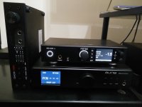
The big transformer would give me more options to also use the PSU for other applications. I am still testing the RME and I am not yet sure if I will keep it. I will also test a Mytek brooklyn DAC+ and Chord Qutest. For the latter I build a 5V PSU with a micro usb cable.
I found it more technical sounding than the other two. Although I loved its functionality. Best with the most natural high definition was the Benchmark. Much more expensive than the other two nonetheless. But I learned from its owner in Thessaloniki that the RME did audibly better with an L-adapter later on. Wasn't designed yet when I had it around so I listened to it with its stock SMPS brick only. Aune was second best soundwise and arguably best value for money.
I found it more technical sounding than the other two. Although I loved its functionality. Best with the most natural high definition was the Benchmark. Much more expensive than the other two nonetheless. But I learned from its owner in Thessaloniki that the RME did audibly better with an L-adapter later on. Wasn't designed yet when I had it around so I listened to it with its stock SMPS brick only. Aune was second best soundwise and arguably best value for money.
I received the boards and mini kits from TeaBag a few days ago. A chassis plus all other parts have been ordered to build the first PSU for the RME.
regards
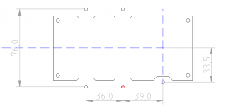
I am looking at using a Hifi2000 GX288 enclosure as heatsink for the PSU. So i came up with this drill pattern for D12-D15 and Q2

Next to that I have a few questions:
-When soldering Q2 in this way to the PCB one has to be careful with D11 not touching the legs of Q2. Who has been there and done it?
-By looking at the parts i have in the minikit from TeaBag it looks like I only need an isolation pad for Q2 and that i do not need isolating grommets for the screws.
I will just use a tiny bit of thermal compound. Is this correct?
thank in advance
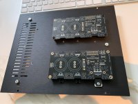
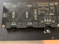
In the first step I drilled all holes in the base plate of the enclosure and tapped m3 thread for the PCB standoffs and for fixing the transistors. The enclosure can fit two PCB's. I start with a 12V and later I will add a 5V power supply in the same housing. The pictures show the first fit, nothing is soldered yet. I will start by the small parts first.
https://www.diyaudio.com/forums/attachment.php?attachmentid=941274&stc=1&d=1618144179
https://www.diyaudio.com/forums/attachment.php?attachmentid=941275&stc=1&d=1618144179
https://www.diyaudio.com/forums/attachment.php?attachmentid=941274&stc=1&d=1618144179
https://www.diyaudio.com/forums/attachment.php?attachmentid=941275&stc=1&d=1618144179
Attachments
I build everything, and I did not expect any issue. But after powering up i only measured a few mV at the output. Both pins measure around 12.45V to ground. These is no voltage drop over D11 and al legs of Q2 also are around 12V.
not sure what went wrong. The LED block is located with the small chamfer towards the pot (as indicated on the PCB).
not sure what went wrong. The LED block is located with the small chamfer towards the pot (as indicated on the PCB).
- Home
- Amplifiers
- Power Supplies
- L-Adapter


