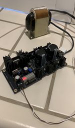
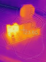
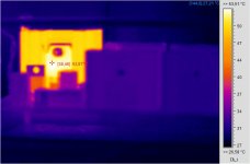
OK - I've now hooked it up to just the Sonore Microrendu. Feeding it with a 6.3v 3A R-Core transformer. Rectified DC voltage is 9.6v and the output is adjusted to 6.1v. The Microrendu wants a 1A power supply, so the pass transistor should be dissipating up to 3.5W, depending upon the actual power draw. I took a few pictures showing the thermal profile. At this power level, temperature rise is pretty modest.The first use will be a Sonore Microrendu . . .
I added a snubber to the transformer and also played with the polarity of the transformer secondary. In various digital projects, I've found that one orientation of connection from the transformer secondary to the power supply sounds better. This was true for the L-adapter, so I'd encourage people to try swapping the 2 AC leads connecting to the board and seeing if one sounds better.
Attachments
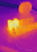
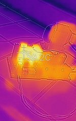
And now I've hooked up the Khadas Tone Board DAC, which draws another 0.5A from the power supply. Rectified DC voltage drops to 9.14v with the added load and the temperature of the pass transistor rises a bit. Theoretically the addition of the Khadas adds another 1.5W of thermal power for the pass transistor to drop (9.14v - 6.1v)*0.5A. But the drop in the rectified voltage means the base thermal dissipation is a bit lower. Temperature of the pass transistor rises from 32.1C to 39.2C. Still quite reasonable. But the pass transistor heat shink might be marginal for a full 8A load.
Attachments
Yes, it's an old Flir One for ios. I checked and I bought it almost 4 years ago. The software is getting a bit buggy but it still works well enough for my purposes.Nice thermal images. Coming from a FLIR?
I should mention that the combination of the L-adapter and microrendu and Khadas Tone Board is sounding very good. It's a nice step up in sound quality from the simpler LM317 based supply previously in use. So you've got another grateful DIY fan. Thanks again.
Uneven Twin Secondary loading.
Hi, I have a Transformer Question.
Some explanation of the set up is needed.
I will be running a RPi 4 so 5.1v 3 amp needed.
I will also be running a digital AES output Hat board.
This Hat runs 5.1v and <0.5 amp
The hat can be powered in one of three ways, in order of Manufacturers preference:
1. Separate supplies for Pi & Hat.
2. Power the Hat and run the Pi off this through the GPIO socket.
3. Power the Pi and run the Hat off it through the GPIO socket.
The Hat has jumpers to allow selection of one of these three hook up variants.
So I will be using option one and building two L-Adapter boards.
I am struggling to find 9V single secondary Trannies to supply them, they all seem to be dual secondary's.
So can I run both L-Adapter boards, one from each of the twin secondary's?
The Pi 4 has the biggest current draw and will require a min 30VA, so a 0-9v 0-9v 60VA is the min requirement. Yes?
My question is this:
Can I run these two, quite different loads, one on each secondary output, without issue?
My worry is it may induce mechanical noise of some sort in the windings, or am I wrong about this and worrying unnecessarily?
Note I will be using an encapsulated Toroidal Transformer.
Last edited:
IMHO if you will go two L-Adapters its a pity to share the transformer although you can. Go with separate transformers also if possible. Not a great performance difference, but the bit better thing its there. Unless its a financial and space concern. 60VA should suffice, yes.
In any case isolated secondaries on shared core can be used for different circuits and loads with no real concern beyond not to exceed the current spec of each winding. That is what multiple secondaries transformers traditionally do, they serve all power needs centrally. Especially in tube audio you may see dramatic secondaries contrast as high voltage mA level outputs for B+ rails serve along with 6.3V and 5V high amperage outputs for heaters sharing the same iron core. Thin and thick wire pairs coming out side by side.
In any case isolated secondaries on shared core can be used for different circuits and loads with no real concern beyond not to exceed the current spec of each winding. That is what multiple secondaries transformers traditionally do, they serve all power needs centrally. Especially in tube audio you may see dramatic secondaries contrast as high voltage mA level outputs for B+ rails serve along with 6.3V and 5V high amperage outputs for heaters sharing the same iron core. Thin and thick wire pairs coming out side by side.
The Pi4b is a bit more power hungry, the stock supply is 3amp, but that is expecting it to be fully utilised, running USB devices. I will be running mine headless most of the time, connected to a NAS device, with wifi and blue tooth disabled. I will only be using a screen/keyboard/mouse for set up and major file organising/housekeeping. The general rule seems to be, work out your current draw and get a tranny twice that capability. I tend to go for three times the current draw or more where I can, I have had occasions when I found this sounded better. My opamp based active crossover (Rod Elliott's project) is one such example, the oversize tranny definitely sounds better, for no obvious reason. I also used a Talema (encapsulated) Tranny on that project.")
Its a fairly lenient design for exact types. It may change its Zo spec or its thermal drift a bit with different same class BJTs but it won't be easily prone to oscillations. It did not show tendencies with a sampling variety during my trials. In any case if you must make a non tried before type substitution do check with the scope that the rail is oscillation free.
And now I've hooked up the Khadas Tone Board DAC, which draws another 0.5A from the power supply. Rectified DC voltage drops to 9.14v with the added load and the temperature of the pass transistor rises a bit. Theoretically the addition of the Khadas adds another 1.5W of thermal power for the pass transistor to drop (9.14v - 6.1v)*0.5A. But the drop in the rectified voltage means the base thermal dissipation is a bit lower. Temperature of the pass transistor rises from 32.1C to 39.2C. Still quite reasonable. But the pass transistor heat shink might be marginal for a full 8A load.
Few more volts to drop... heat! Side note on measurements (on an IC), with the thermocouple on my DMM I got a surface temp of 48°C when the IR camera shows 58°C on the hottest spot of the IC! Scary! Maybe the IR sees "inside" the IC... On a heatsink they are in the same ballpark.
Attachments
That temperature difference computes for Watts burned and RθJC?
No way to know, RθJC not given as it's a SMD DAC chip on a class A output stage. Heatsink side: 56/56°C, other side with spacers // DAC board: 48/58°C... Maybe I'll stick with my Fluke thermocouple and will not borrow the office IR cam anymore, troubles my mind
No clue at all! Sorry for digressing...
Last edited:
. . . Side note on measurements (on an IC), with the thermocouple on my DMM I got a surface temp of 48°C when the IR camera shows 58°C on the hottest spot of the IC! Scary!
That temperature difference computes for Watts burned and RθJC?
I think that Salas has it right. Transistors or ICs on a heatsink always have to be hotter than the heatsink - that's what causes heat to flow from the device to the heatsink. The temperature difference should be the thermal resistance of the interface (degrees C/Watt) times the power being burned in the device. So a device burning 6 watts with a thermal resistance of 1.5W/C will see a 9C temperature difference to the heatsink.
10°C difference depending on the measuring device.
Any way to calibrate them both?
No, if I measure something else there is no difference, these 10°C are only when measuring the IC. On the output stage heatsink they are within the same °C.
But you have a point, the Chauvin Arnoux camera can behave oddly sometimes, as there is air and reflections around, can it be that more IR waves are seen?
Sorry Salas that was just a side note!
- Home
- Amplifiers
- Power Supplies
- L-Adapter