alright been digging the schematic a little bit.
Is there any other less wastefull option instead of the LM339? What other common cheap op amps are possible to use? If not well stick with the LT1800 just asking.
Can I also get component recommendation ? (the D flip flop and the gates A2 and A3)
I assume a simple 5V refference with a TL431 will be sufficient ?
Uhm. Kind of throw that in the bin and be patient. It's not done until it's done. That's why they call it Design and Development. I think you may have had experience of that one...
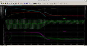
Now with, poorly implemented, inrush current limiting and using a TL494. Yes I hate myself already and yes it was a pain interfacing to it.
No LM339 but this time a single quad op-amp. I'll bear the cost in mind but there are bandwidth and slew rate requirements plus it needs to be rail to rail input and output.
You can worry some more because I have decided to use current transformers. Again, in part, this is error amplifier bandwidth but more importantly power loss in sense resistors.
Picture is start up to 420V @ 315W. Top loss in the limiter, output voltage, input supply and input inductor current. Middle output of current transformers. Bottom output of voltage and current error amplifiers.
...
Attachments
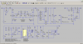
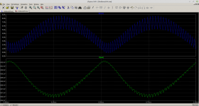
Now with flux balance compensation. The problem is that primary side current is determined solely by the boost inductor. Secondary side current is delivered as primary side transformer magnetising current subtracted from the boost inductor current... modified by the turns ratio. If the primary side magnetising current is unbalanced which it will be because it is a push-pull convertor then things rapidly go to pot. You can't use current mode control, peak or otherwise, on the primary side because it is just going to control the boost inductor current unless you come up with a cunning plan. The simpler cunning plan is to monitor secondary side current where the problem really makes its impact known and then take action on the primary side.
Latest .asc as a .zip plus some words up until the Right Half Plane Zero. This is ifedboost04. Edit the label SNS at the bottom of RT to be GND(global 0) to watch it lose the plot.
...
Latest .asc as a .zip plus some words up until the Right Half Plane Zero. This is ifedboost04. Edit the label SNS at the bottom of RT to be GND(global 0) to watch it lose the plot.
...
Attachments
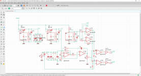
So I have been a doing some operational surgery and this is what I thought up with the currently available parts I have.
Still using the GA3459 transformers (because custom is a no go for now) and going voltage mode flyback.
Not ideal but good enough.
R7 limits max DTC and C7 is the soft start. Each IC has its own bypass cap and so on.
The oscilator (consisting of IC1) is expected to run at 47kHz (enough).
The PSU has two channels that are independednt of each other other than the clock, so there are completely independentally regulated two outputs and each channels can be set at a different voltage and each can provide with a some little discomfort 60W. For a stereo 20W cathode bias or even a 40-50W grid bias it should be sufficient
Everything is overkill and regulated quite nicely. Should give me the stability and nice signal integrity within this monster aswell.
I went full discrete but I dont regret it. This circuit (only one channel) proved to work fine in the past with no hiss or noticeable horrible noise like the one I have right now rocking the TL494.
This doesnt really fit the needs of insanely high power capability but sure is a functional thing for decent power amplifiers and should be relatively silent with a LCLC filter on the output.
Also using a single timebase avoids the problem of whistling and weird stuff when two PSUs have different frequencies and phase shifts and all that weird junk
Unfortunately I came to a screeching halt in the advancements to get another complete and more powerfull redesign of my PSU.
Core reason being: inabillity to make a custom transformer.
I cant find any data or literature on how to make one and there seem to be less than 0 people who actually care to help me.
Manufacturers show me the middle finger not just in terms of actually manufacturing the custom part but also in terms of helping to design one. Nobody wants to help me not even give me the abillity to design one or give me the theory so this power supply is effectively a dead end.
To anyone in the future trying something mad like this: unless you can work with someone who has the knowledge just give it up. Nobody is gonna support you.
Designing a high voltage power supply, with high current capabilities is not an easy feat to accomplish. I believe Coil Craft offers a forward mode transfer that can do 10amps. It may be possible to use two, in parallel to charge a bus (cap bank) to higher voltage, and then use a HV regulator (switch or linear) on the output. I would very much love to build one, but as you have found out, it’s way harder than reading a design book. My desire to build one almost makes me want to go back to college for high power circuit design. If there is a way to help you, let me know. I’ll review the thread, as I have been out of the loop because of job loss, and post the part number of the aforementioned transformer.
A Guide to Forward-mode Transformers | Coilcraft
A Guide to Forward-mode Transformers | Coilcraft
https://register.gotowebinar.com/register/2761521718863155467
Design, Build, and Test a Flyback Transformer - Webinar
Design, Build, and Test a Flyback Transformer - Webinar
Unfortunately I came to a screeching halt in the advancements to get another complete and more powerfull redesign of my PSU.
Core reason being: inabillity to make a custom transformer.
I cant find any data or literature on how to make one and there seem to be less than 0 people who actually care to help me.
... there are books about, one being Switchmode power supply handbook by Keith Billings ibsn 0-07-005330-8
This is only the start of the science around magnetics design, switchmode and applied techniques and will change one´s approach. Physics with some math and a proper lab bench with decent quality scopes, isolating power supplies will be required but far more is the understanding and skill from time served work. From the previous application lab generation 1950-1980, one never threw away those application and data books from Unitrode which is now Ti. With this was the pure analogue world were some of us excelled. Also ferrite material product books....from Philips, Magnetics, Micrometals and others are a mime of information. These are absolute ´gold dust´ material.
Now the web does have alot of application notes but remember one´s own design request; create a specification and work around it; if it is workable esp which switching topology would be best.
A software redesign of a switch mode power supply is a very risky undertaking without analogue experience; spikes and strange things happen with mysterious failures that will often test the skill of the the designer. On many occasions I had to resort to microwave layout techniques with the adapt use of a good soldering iron to get the results.
It is such a shame these days that I come across so much valuable previous curriculum material being scrapped with educational reforms, often just to suit the wasteful learning trends of today. Without magnetics and core subjects of physics, the world wouldn´t tick anymore.
Keep one´s hand on the tiller one will need it.
Viva analogue.
rich
Attachments
See Development topic 12=>200-450V 100mA flyback.
If you don't mind the 12V primary there is the : TI-EF25-1068 FERYSTER - Transformer: impulse | power supply; 45W; Works with: UC3843 | TME - Electronic components
Personally i was thinking of paralelling two of those for higher currents, i just need to change the circuit a bit so that the mosfet is turned off harder.
I know you use eagle as well, so see attached my current progress with the flyback test board.
Me thinks we might need to add a 4420 mosfet driver between the 3843 output and the FET, so the gate is driven hard.
Attachments
Most people who have had extensive experience in designing up and testing smps transformers have done it as a job, and based off a past that shows they can understand and appreciate detailed electronics and magnetic theory, and can access and learn from previous similar products and a wide variety of design material that is available when a reasonable amount of effort is applied to chase down relevant documentation.I cant find any data or literature on how to make one....
Some magnetics and control IC companies have provided tutorials and app notes, with the aim of easing professional designers through the process of collating all the raw data (ie. magnetic core and control IC implementation data) and giving an example design path and example experimental results. Most companies that have been down a smps development path for a particular product would not make the development and verification type dossier available for public scrutiny, nor should they, as it is in-house blood and sweat to achieve and has a value. There are literally thousands and thousands of products that would have design and testing dossiers sitting in filing cabinets that justify and define how to make a reliable smps that meets the product specs.
If you want to become a racing car driver then there is a lot of work and effort and opportunity and time needed to build one's experience.
It is a lot easier for others to assist if your past simpler projects are all fully documented and can be seen to show you are not missing some aspect or other of understanding or awareness, and then your present project is similarly documented and detailed down to the nth degree that there is not something missing in preparation, and that forum posts are restricted to small bite-size technical uncertainties that may be easy to respond to.
That may be difficult to appreciate for an 18 year old that hasn't had the luck so far to work through a few more years of solid theory and practical grounding, or gained a foothold in a company that does smps design/manufacture which you can leverage off for fast-tracked experience.
There are lots of calculators available for transformers in the diySMPS forums. Page TitleUnfortunately I came to a screeching halt in the advancements to get another complete and more powerfull redesign of my PSU.
Core reason being: inabillity to make a custom transformer.
I cant find any data or literature on how to make one and there seem to be less than 0 people who actually care to help me.
Manufacturers show me the middle finger not just in terms of actually manufacturing the custom part but also in terms of helping to design one. Nobody wants to help me not even give me the abillity to design one or give me the theory so this power supply is effectively a dead end.
To anyone in the future trying something mad like this: unless you can work with someone who has the knowledge just give it up. Nobody is gonna support you.
Sorry I have not read this thread, just dont have the time now, but from just a few posts above it seems one challenge is the flyback transformer.
I did one with a 350V output once, from 24-48V input, and found the best way was to make four secondaries, each stacked on each other (series connection) and each rectified by a small and low charge diode. All windings one layer, one layer tape between, primary windings interleaved between each secondary and in parallel.
The bobbin was increased in diameter using paper so the first winding (inner) was a little further out than stock, to reduce fringing losses. That helped a lot. It also makes each winding more similar since the inner most one isn't so small in diameter compared to the outer most.
It runs at > 400kHz so it does not need many turns, making it relatively easy to wind, can't remember how many turns but think less than 10 on the primary and twice that on secondary, same wire, just two in parallel for the primary, on a type RM8.
Few turns, same wire, and those transformers are not that difficult to make.
- Home
- Amplifiers
- Power Supplies
- Powerful SMPS for tube ampifier