It's all gone a bit ding dong. Let's have a quick look at a push-pull supplied from 12V.
Tubes wants 300W and taking a guess at nominally poor efficiency into account the starting point is 360W input. From 12V that's 30A.
You want to regulate things so say the convertor operates at a nominal 80% duty cycle... could be 90% but 80% pushes the peak current drawn up to 37.5A
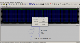
With an IRFZ44 using just the 25C RDSon.. Picture. That's 16 Watts per device and that's before you factor in turn on and turn off losses rise and fall plus capacitive switching losses. Then you get to lump in snubbers to cope with transformer leakage unless you let the devices undergo avalanche breakdown, that's allowed if the device is specified for repetitive operation but the power loss is still there.
It really all looks very nice in a picture but when you look harder things rapidly fall to pieces. My proposal will probably do the same.
Then have a think about your shiny CE marked Mains to 12V power supply. Is it going to like having its output hammered with a 37.5A 80% duty cycle square wave? I doubt you would get an answer from the manufacturer and anyway... to my mind that sort of stuff is provided to supply 12V spot lights or strings of LEDs.
Either way you will end up having to tag some serious amount of filtering onto the input of your convertor to avoid upsetting the upstream convertor.
Then we get into the TL494/SG3525 voltage mode controller regime. The web is full of knock off bright ideas for those things used with push-pull convertors to supply car power amplifiers. The example given by Tubes at least manages to include an output inductor. Most people go raw Meh and possibly rely on transformer leakage to prevent things blowing up when you first switch it on and then parallel 20 IRFZ44's per leg for safety.
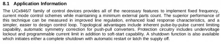
I've already mentioned that my proposed convertor will suffer from flux walking. I'll explain why later. However voltage mode control of a push pull convertor suffers from exactly the same problems. This is why they came up with the UC1846 or similar current mode controllers for push-pull convertors.
https://www.ti.com/lit/ds/symlink/uc1846.pdf?ts=1591043958190
The magic words are automatic symmetry correction.
I get the desire to use what appears to be easily available to you but there is not much point if you end up with a broken thing that sort of works until it does not.
Elsewhere. Yah... We can do a TL431 with an opto for feedback or something else.
...
Tubes wants 300W and taking a guess at nominally poor efficiency into account the starting point is 360W input. From 12V that's 30A.
You want to regulate things so say the convertor operates at a nominal 80% duty cycle... could be 90% but 80% pushes the peak current drawn up to 37.5A
With an IRFZ44 using just the 25C RDSon.. Picture. That's 16 Watts per device and that's before you factor in turn on and turn off losses rise and fall plus capacitive switching losses. Then you get to lump in snubbers to cope with transformer leakage unless you let the devices undergo avalanche breakdown, that's allowed if the device is specified for repetitive operation but the power loss is still there.
It really all looks very nice in a picture but when you look harder things rapidly fall to pieces. My proposal will probably do the same.
Then have a think about your shiny CE marked Mains to 12V power supply. Is it going to like having its output hammered with a 37.5A 80% duty cycle square wave? I doubt you would get an answer from the manufacturer and anyway... to my mind that sort of stuff is provided to supply 12V spot lights or strings of LEDs.
Either way you will end up having to tag some serious amount of filtering onto the input of your convertor to avoid upsetting the upstream convertor.
Then we get into the TL494/SG3525 voltage mode controller regime. The web is full of knock off bright ideas for those things used with push-pull convertors to supply car power amplifiers. The example given by Tubes at least manages to include an output inductor. Most people go raw Meh and possibly rely on transformer leakage to prevent things blowing up when you first switch it on and then parallel 20 IRFZ44's per leg for safety.
I've already mentioned that my proposed convertor will suffer from flux walking. I'll explain why later. However voltage mode control of a push pull convertor suffers from exactly the same problems. This is why they came up with the UC1846 or similar current mode controllers for push-pull convertors.
https://www.ti.com/lit/ds/symlink/uc1846.pdf?ts=1591043958190
The magic words are automatic symmetry correction.
I get the desire to use what appears to be easily available to you but there is not much point if you end up with a broken thing that sort of works until it does not.
Elsewhere. Yah... We can do a TL431 with an opto for feedback or something else.
...
Attachments
Last edited:
before going into the actual design of the power supply- here is a thought of mine.
Id like to make a line of products..that said voltag range of 300-500V and model with power varying from 60W-120W-300W (thats only B+ power)
Every power supply would have a -120V rail which would be 5W capable and every power supply will have a heater output aswell that would do 6,3V or 12,6V.
I plan to do this : Make the B+ power supply completely separate and then on the same pc well put a different power supply that would regulate the 6,3Vout and also generate the -120V bias voltage. I assume it would work better on the heater supply just because tube heaters are basicallly constant load and you have bias voltage applied constantly (so when you flip the standby switch it already has bias on it). And really the HV will have a lot of dynamic loads and we dont really want our bias to fly arround or the heaters recieving sudden spikes (which the pream tube would not really apprechiate)
what would be the best topology to achieve these things ?
Lets say at most a mono block would need 60W B+, Lets say its two output tubes and three preamp tubes..5A at 6,3V. Thats round 30W.
Lets assume most stereo amps will need 2A each power tube (4tubes for pushpull) and at least 6 preamp tubes soo that would basically 10-11A.
I would assume one using a 60W PSU would be a SE stereo or mono or monoblock pushpull
One using a 120W would use it for pushpull stereo each channel 50W
One using a 300W module would be running tubes at 500V-600V KT88 KT100 KT120 possibly KT150s and run them as hard as possible Its quite easy to get 80W with KT88s I wonder what the 150s could do with reduced anode impedance.
Thats how I see it.
Point taken about the current load on the pre-built supply, I was actually looking at a 24V supply, not 12, so the current would be 1/2. Higher voltages are available. Up to 60V. I am still very concerned about the problems of getting a mains operated device certified. The way I see it, the cost of being certified is greater than any foreseeable profit. If the market was large enough, someone would have done it already. That is my only objection to going full line in.
At 100kHz putting a kinder load on the supply should not be very costly. Going mains input means EMI filtering is required. The only rail that need fair regulation is the 6.3V line.
At 100kHz putting a kinder load on the supply should not be very costly. Going mains input means EMI filtering is required. The only rail that need fair regulation is the 6.3V line.
Good morning again. OK, you win... kind of. The topology should work with any input voltage within reason but of course more will be better in terms of overall efficienct. I'll adapt the model for a 48V input and tie down the control circuitry and other bits closer to a final result and see how the numbers run. This does not preclude going offline so that sounds like a win for everyone. I'll post some results later in the day.
An afternoon update. Tubes was right unless Cat disagrees. Without the PFC requirement and using a regulated input things get better in terms of loop bandwidth achievable output ripple and other things.
Offline is still not discounted.
You may have noticed that I am still floating a concept so things can still go horribly wrong. However in going back to the drawing board and looking at things in more detail, refinement cough..
I know have a better idea as to how the thing really works or should work and behave beyond my original thoughts. This is in part why I always bung things in Spice for a reality check.
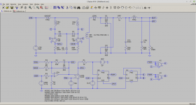
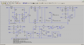
We end up with a Current Fed Push-Pull Boost convertor and it might be possible to implement it using an SG3525 with some assistance from a few external components. That's tentative.
Latest LTspice .asc file attached. This is from 48V in to 420(ish)V out at about 360W. No voltage feedback as yet. However, you might hate me for it but, you Valve Heads just love your CLC filters so I've bunged one in to get the output ripple down, 90mV p-p
That will affect the voltage loop compensation but we know it's there and subject to analysis.
There are still concerns about added complexity in the transformer, leakage inductance and minimum load but things still look doable.
...
Offline is still not discounted.
You may have noticed that I am still floating a concept so things can still go horribly wrong. However in going back to the drawing board and looking at things in more detail, refinement cough..
I know have a better idea as to how the thing really works or should work and behave beyond my original thoughts. This is in part why I always bung things in Spice for a reality check.
We end up with a Current Fed Push-Pull Boost convertor and it might be possible to implement it using an SG3525 with some assistance from a few external components. That's tentative.
Latest LTspice .asc file attached. This is from 48V in to 420(ish)V out at about 360W. No voltage feedback as yet. However, you might hate me for it but, you Valve Heads just love your CLC filters so I've bunged one in to get the output ripple down, 90mV p-p
That will affect the voltage loop compensation but we know it's there and subject to analysis.
There are still concerns about added complexity in the transformer, leakage inductance and minimum load but things still look doable.
...
Attachments
In respect of available outputs the whole point of trying to go the current fed boost route beyond its input ripple being benign to the upstream convertor is that it behaves in a similar way to flyback in that you do not need output filter inductors. Assuming tight coupling then all windings on the transformer will track each other give or take diode drops.
Other than winding complexity if you want another output you just add another winding or tap off one that is available. The main limitation is the volts per turn resolution. In the above example I have guessed at an ETD39 with 20 primary turns and 150 on the secondary. Don't get excited it may not work that way. I just get to make broad guesses.
That gives you 2.8V per turn. Tubes has already mentioned a desire for a post regulator on B+. This B- is such low current it might as well have one as well. That leaves you with the heaters. It's kind of bear such considerations in mind but do not think too far ahead. My feeling is that this can all be done on one convertor if you accept that when you move too far in terms of versions from a base then at a minimum you will be looking at the same type of transformer but with different turns ratios for a different model.
Something like that anyway.
I was thinking separate B+ spully and separate heater and B- supply for only the reason that "i have a feeeling" with the dynamic load that the B+ is going to have going on it might modulate stuff into B- or the heater winding. If were doing a 300W converter and a tube amplifier of that power (lets say with KT88 150W output) at the B+ of 600V the tubes will be biased to lets say 35W each (that gives you 70W totdal power draw from B+). Until you keep within those 70W of power youre fine as soon as youll start cranking that volume up youre going to get peak loads of up to 300W. Either needs compensating in the feedback which then reduces voltage feedback precision or I have no idea.
I have still not fully given up on the mains converter. But I guess starting with a LVDC-HVDC converter will be much easier. Maybe some other time when it makes enough money to do the certiffication of a mains supply..just fantasizing.
If you have a IC suggestion that would work best for this application then we could use that aswell.
About that transformer of yours:
20turns and 150 turns does not sound bad..so its 10,10 ? (20 centertapped) ?
also at 360W its 7A of current. That needs quite the thick wire. When I was disecting smps transformers from pc powersupplies (from old ones that used to create all voltages in one stage) I noticed that they have not used thicker wire but they paralelled lets say 4 strands of wire and wound them flat. Does this do any good or i can just buy thicker wire?
Secondary wire thickness will have to be rated to 1A at least. And I assume proper thick glaze will be needed on it too.
Yeah, that is the chip I think is best. But, change the freq then you need to change the transformer.
Have you done an IM or FFT test? If so, do you seen PS residual noise?
I haven't, I just don't see any HF on the output whatsoever (scope).
Mouser prices are truly decieving. The delivery service is 50 euros. Not so cheap anymore.
In Canada, they charge zero if you order more than 100$.
It's all gone a bit ding dong. Let's have a quick look at a push-pull supplied from 12V.
Tubes wants 300W and taking a guess at nominally poor efficiency into account the starting point is 360W input. From 12V that's 30A.
You want to regulate things so say the convertor operates at a nominal 80% duty cycle... could be 90% but 80% pushes the peak current drawn up to 37.5A
With an IRFZ44 using just the 25C RDSon.. Picture. That's 16 Watts per device and that's before you factor in turn on and turn off losses rise and fall plus capacitive switching losses. Then you get to lump in snubbers to cope with transformer leakage unless you let the devices undergo avalanche breakdown, that's allowed if the device is specified for repetitive operation but the power loss is still there.
It really all looks very nice in a picture but when you look harder things rapidly fall to pieces. My proposal will probably do the same.
...
My main ATX powered rig puts out over 70A of clean 12V power. The boost modules I use use YP1906 or some other unknown Hyundai MOSFET, but the IRF3205 works well in it's place.
Right now, I'm using a cheap-ish 500W ATX to power an integrated amp using three different boost modules, and a handful of other parts. The IA has 20 tubes in it, the outputs being 6P31S. It barely gets hot.
Except for the conversion loses, why not build a mains to 12V to HV supply? You need the LV for controls and heaters anyways?
Hi Team. A minor incremental update.
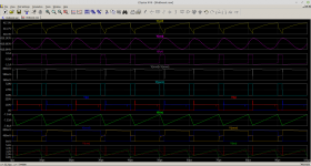
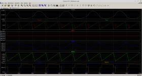
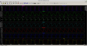
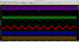
Having gone back and updated the timing of the PWM vs Push-Pull drive waveforms things make more sense and the minimum load requirement may have gone away. This one is without the CLC. Just a C.
No .asc file because I sort of hacked it. I kind of know how these things work so I get to scribble on a bit of paper and tap the calculator. There is some underlying theory to this which I hope to give but this is a sort of cut and try.
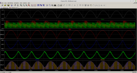
You might/should notice that ripple in the VEA, voltage error amplifier, and output voltage is uneven. This to me is indicative of flux walking in the main transformer. Either it will be a real problem that can be dealt with or it will be dealt with.
In respect of transient performance the other picture is the loop tracking a 1KHz demand from 150mA to 750mA. At 420V that's about 63W to 315W. The sky has not fallen in because this is with a 1uF output capacitor. Switch Mode Power Supplies are an interactive pain. The 1uF cap reduces inrush current but we can use a bigger one if we take action elsewhere.
In respect of the transformer. The design is another iterative pain. Rule of thumb is you target 4A/mm^2 as the current density in the windings. Yes proximity and layer effect apply so you will get multifilar windings. I've attached a program I wrote to do this some time ago. It is based on a paper by Dowell posted to me by a librarian from Philips in a former life.
Words from Unitrode.
https://www.ti.com/lit/ml/slup125/slup125.pdf
Trust me. I'm not going to design a transformer that someone else would hate to wind, well, almost. In terms of sourcing wire, litz, TEXe, and dare I say foil this can be sorted. End of day I can do that locally or get someone to wind one for me and send it to you in the post.
...
Having gone back and updated the timing of the PWM vs Push-Pull drive waveforms things make more sense and the minimum load requirement may have gone away. This one is without the CLC. Just a C.
No .asc file because I sort of hacked it. I kind of know how these things work so I get to scribble on a bit of paper and tap the calculator. There is some underlying theory to this which I hope to give but this is a sort of cut and try.
You might/should notice that ripple in the VEA, voltage error amplifier, and output voltage is uneven. This to me is indicative of flux walking in the main transformer. Either it will be a real problem that can be dealt with or it will be dealt with.
In respect of transient performance the other picture is the loop tracking a 1KHz demand from 150mA to 750mA. At 420V that's about 63W to 315W. The sky has not fallen in because this is with a 1uF output capacitor. Switch Mode Power Supplies are an interactive pain. The 1uF cap reduces inrush current but we can use a bigger one if we take action elsewhere.
In respect of the transformer. The design is another iterative pain. Rule of thumb is you target 4A/mm^2 as the current density in the windings. Yes proximity and layer effect apply so you will get multifilar windings. I've attached a program I wrote to do this some time ago. It is based on a paper by Dowell posted to me by a librarian from Philips in a former life.
Words from Unitrode.
https://www.ti.com/lit/ml/slup125/slup125.pdf
Trust me. I'm not going to design a transformer that someone else would hate to wind, well, almost. In terms of sourcing wire, litz, TEXe, and dare I say foil this can be sorted. End of day I can do that locally or get someone to wind one for me and send it to you in the post.
...
Attachments
Well that sounds all nice..
Lets say you do the math design the circuit and all. Okay. Ill take the part in PCB design and physical manufacturing, except for the transformer if you can get someone to make one. Id like to avoid winding one at all costs
Ill go trough and read the PDF file..Looks like a nice bed time reading for me.
So now that we have a design thats expected to work could you perhaps take a look at a IC that could do this for us ? I would prefer with minimum external components for obvious reasons but I am open to any solution. Even discrete all tho I would like to avoid that if possible.
Also just a personal prefference: I would still use that CLC on the output. I know its not necessary but just a personal prefference. CLC filter cant hurt that much can it?
So, I had to take a break for birthdays and stuff.
Morbid uses a straw man to create an argument of incredulity to dismiss my suggestion that buying a CE certified power block to simplify the process.
My initial check of the CE cert cost has come up with a silly range of cost, $64-64,000. Some products can be self certified. I doubt a line voltage product falls into that. I shudder to think of the legal liability issues. Also, the 100kHz operating freq sounds like something requiring EMC testing. A lab is likely to be needed for that, because of special equipment needed. My initial survey suggest that a non CE device connected to a CE certified device may not require it's own documentation.
I ran some numbers using a 12V input and got peak currents similar to Morbids numbers, but with the same initial conditions and a 60V input,the highest voltage from the OEM PS supplier, peak currents were proportionally lower.
The unit or units, Cat wants to make are in the range of, but not the same as, what I want/need. He is free to pursue any design he chooses.
Sorry about the 'straw man'. You do not know until you properly 'run the numbers'. As I suggest for similar power levels the only major change may be the transformer windings otherwise an adjustment over 25% is likely to be possible for B+. In the case of B- given its low current a linear post regulator will allow a much wider operating range. For filament supplies a switching post regulator would do the job. There is a thing called a leading edge modulator that would integrate with the main transformer or... we could use Mag Amps because they are green.
Happy Birthday.
Happy Birthday.
Last edited:
Which means you have nothing yet. The controller is the thing that can misbehave in a thousand ways; without it you are completely in the dark. Do more simulations with the controller chip included to avoid costly outcomes.CaterpilarSK said:Well that sounds all nice..
[snip]
So now that we have a design thats expected to work could you perhaps take a look at a IC that could do this for us ? I would prefer with minimum external components for obvious reasons but I am open to any solution.
UCC35705/6. Unfortunately there does not seem to be a Spice model available for it so I have had to roll my own which, to your way of thinking means we still have nothing.
Sorry Team. Project cancelled.
Rename .txt to .asy
...
Sorry Team. Project cancelled.
Rename .txt to .asy
...
Attachments
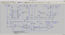
Now with added UCC35705 and a few extra tweaks. The Push-Pull square wave drive has to be synchronised to the PWM. That's done with the LM339 comparator sensing the timing triangle, TRI, on the UCC35705 against half of VFF which sets the ramp peak. That might be subject to further processing.
Some other words...
For voltage fed Push-Pull you need devices rated at a minimum of 2VIN. For current fed boost Push-Pull you need devices rated at a minimum of 2Vboost, VBST on the circuit. On top of either of those you have to add more for the leakage inductance spike. I've scaled things for 60V on VBST needing 120V devices but actually requiring 150V ones.
It's a Switch Mode power Supply. Everything is a trade off against competing things.
Everything attached in the zip. Fingers crossed that will work with a bit of fiddling should you be interested.
...
Attachments
- Home
- Amplifiers
- Power Supplies
- Powerful SMPS for tube ampifier