I thought it worth making that post - even though this is a diy forum, I would professionally be concerned about a smps designer that gave a project status report with
A nice aspect of smps design is that it covers such a wide range of technical aspects - of which any one can trip up a prototype until adequately appreciated and worked through. PCB design is just one aspect where noise level can increase with an output variable and then reach some limit on a feedback or local supply rail such that the controller gets confused.
which is exactly what happened. I didnt think trough the component values correctly otherwise the PCB is even shielded (using one copper layer as solid groundplain shield) running short high current lines, track lenghts kept equal.
The only thing I didnt do and I now regret not doing is givving the 494 a discrete regulator so the garbage from switching would be filtered with a fast LDO, further ensuring stability.
I found a much better IC for the job. LM5021. Im determinde to use that and this time go mains power with the coilcraft HA4060.
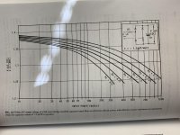
The HA4060 is rated 2A peak @ 120V. That's consistent with a 4.5uS on time which agrees with the measurement frequency of 100KHz. 50% duty cycle for a single switch convertor. At 230VAC/311DC your duty cycle will be 17%. You are strictly limited to that 2A peak current. Your convertor will operate with discontinuous current, good and bad, and your strict power limit will be 50W. If you can't do these sort of sums and prefer to thrash about in the dark then you are on a road to nowhere.
If you’re still planing a 500Vdc output be careful not to exceed the voltage at the HA4060 transformer, which is rated for 500Vdc.
I am aware of the 500V max output. I have yet to use it for audio on that voltage. The Mullard 20W amplifier runs of 420V I only tested if its capable of 500V at 50W
So here is a question. For those of you who make mains powered SMPS, how do I calculate the mains side capacitor bank capacitance.
Peak current 2.5A
Voltage on the filter caps = 120VDC-380VDC
Switching frequency = 100kHz
I have absolutely no clue how to get this value. I will also build a proper mains input (noise filter and all that)
Peak current 2.5A
Voltage on the filter caps = 120VDC-380VDC
Switching frequency = 100kHz
I have absolutely no clue how to get this value. I will also build a proper mains input (noise filter and all that)
The amount you will need depends on what you want for the ripple (both voltage and RMS current) on DC link to be and how much reserve energy is needed for regulation, transients and holdup time. A guess a good rule of thumb would be a minimum of 1.5uF/W, if you are using a full wave bridge rectifier and single supply.
You will most likely want to construct a soft start circuit for the charging of those caps and make precautions for AC surges.
You will most likely want to construct a soft start circuit for the charging of those caps and make precautions for AC surges.
Attachments
Last edited:
The amount you will need depends on what you want for the ripple (both voltage and RMS current) on DC link to be and how much reserve energy is needed for regulation, transients and holdup time. A guess a good rule of thumb would be a minimum of 1.5uF/W, if you are using a full wave bridge rectifier and single supply.
You will most likely want to construct a soft start circuit for the charging of those caps and make precautions for AC surges.
Thank you very much sir.
With more than enough reserve ill go with 150uF roughly. Using two 56uF 450V capacitors and two 10uF 450V low ESR cap. That should take care of it.
AC surge will be taken care of in the AC input filter.. PTC should be sufficient. For the secondary side the SMPS chip has a soft start pin and I will surely use it.
I haven’t used a PTC thermostat, only the negative verity. Is the PTC used in place of current sense resistor?
ah crap sorry I'm dumb. I wanted to say NTC and then for some reason I did that. Sorry I meant to say NTC .
To an extend, yes. The 12-24Vin to 300-500Vout has been finished and I will never ever look back at it. Could have been done smarter but because of time and money and just the pure will has decreased to zero.
I have designed a mains to 300-500vout version, which kind of works but the regulation is problematic (feedback maybe not having enough open loop gain). It sort of works but since the very negative feed back from forums I reduced my efforts to minimum and gone back to transistors amplifiers and laboratory power supplies (I have prioritised my 30V3A bench PSU design above all)
There is no place for me to publish my design, findings and the data I collected. Because nobody cares or is interested and a lot of people went against me that I even dare to create such a power supply for vacuum tube amplifiers despite all three advantages..
No power supply manufacturing company had any interest in helping. (Including mean well even tho they said they support s lot of student projects but I guess me asking for actual advice instead of a product is not student support even tho I am a student)
So I kind of pushed the whole thing into the backround noise of my lab.
I was hoping for a more positive end story. I am very interested in a line input, 90-270V, 200W 420-430Vdc supply. Have you considered a push-pull or half bridge arrangement? Has anyone got a useful opinion on an SG3524 or 3525a? I've seen circuits using it to make DC to 220Vac inverters. I don't think it will be a problem to use it line in at 100kHz.
Hello. It kind of suprises me people still manage to dig this dead thread up. Unfortunately times arent as good as they could be and I truly dont have time to do any electronics. Your IC suggestion isnt bad at all but there is one problem and that is the transformer.
There are no comercially available transformers for such a power supply I want to build. Every manufacturer refused helping me soo. Kind hit a roadblock to be hones. But its not that emotional anymore. Just kind of gave up on the project
There are no comercially available transformers for such a power supply I want to build. Every manufacturer refused helping me soo. Kind hit a roadblock to be hones. But its not that emotional anymore. Just kind of gave up on the project
Hello. It kind of suprises me people still manage to dig this dead thread up. Unfortunately times arent as good as they could be and I truly dont have time to do any electronics. Your IC suggestion isnt bad at all but there is one problem and that is the transformer.
There are no comercially available transformers for such a power supply I want to build. Every manufacturer refused helping me soo. Kind hit a roadblock to be hones. But its not that emotional anymore. Just kind of gave up on the project
Sorry to hear you gave up. I am disabled, but I do not and have not given up. Other aspects of your life are apparently more important. I get it.
Making a transformer is no big deal, all that is needed is to know how many turns and how big a core.
If it was so easy. Firs of all I am running a switchmode transformer here so its the same math except for different frequencies. And you also have to think winding DC resistance and interwinding capacitances... Also you need a big enough core with high enough permeabillity and there is quite a bit. Not saying its impossible but definitely beyond my scope of knowledge and I can barely find porper literature on switchmode transformers for different topologiex (not only flyback but all of them).
wow now thats a usefull tool right there. Archiving that one thank you. Wow this thing offers quite a rande of cores and stuff
I found it in a search on this forum and I waited to read your thread before trying it. I am still figuring out it's features. If you can order from "The usual suspects" I figure you can get the cores you need. Wire is EZ. I recommend Litz wire. In the USA, small amounts can be gotten from a place called Remington wire, or something like that. As always, Google is your friend. I am a total novice with SMPS, but I see the advantages and I want to learn.
Well I am from the EU (Slovakia is bang on center). I buty stuff from TME. The core are no issue neither are the wires. I have been experimenting with audio transformers for microphones (trying to replicate a neumann U67). I dont have a coil winder soo thats a bummer but for SMPS transformer not much wire is eneded anyways.
Ill absolutely take a look and try. I have made a test rig (all discrete power supply). It should be able to test whatever I throw at it.
It will unfortunately have to wait till summer because currently teachers throw more homework at us than stalin did T-34s at kursk. Also I am a beekeeper and currently thanks to the weather tought times are coming so I have quite the work to keep up with in the meantime but ill make sure to spend my 3am computering on this then
I really wonder what are the standard voltages for a SMPS for a tube amplifier?
Is there a guide line to build a standard model?
I believe I might put that on my list if its something within
Standard specs / voltages
Please put specs in a way like voltages, current, regulated or not
Mention each rail separately please.
If detailed schematic shows the final wiring will be great.
Thanks
- Home
- Amplifiers
- Power Supplies
- Powerful SMPS for tube ampifier