Well I am from the EU (Slovakia is bang on center). I buty stuff from TME. The core are no issue neither are the wires. I have been experimenting with audio transformers for microphones (trying to replicate a neumann U67). I dont have a coil winder soo thats a bummer but for SMPS transformer not much wire is eneded anyways.
Ill absolutely take a look and try. I have made a test rig (all discrete power supply). It should be able to test whatever I throw at it.
It will unfortunately have to wait till summer because currently teachers throw more homework at us than stalin did T-34s at kursk. Also I am a beekeeper and currently thanks to the weather tought times are coming so I have quite the work to keep up with in the meantime but ill make sure to spend my 3am computering on this then
I forgot about TME. I'm having trouble figuring out what are the cores specified. And the input your own data feature doesn't seem to work.
not sure if any voltage standard exist, except for filament voltage. I need about 420-430V at around 0.2-0.5A. to drive a linear regulator for clean up and to lower output impedance.I really wonder what are the standard voltages for a SMPS for a tube amplifier?
Is there a guide line to build a standard model?
I believe I might put that on my list if its something within
Standard specs / voltages
Please put specs in a way like voltages, current, regulated or not
Mention each rail separately please.
If detailed schematic shows the final wiring will be great.
Thanks
There really is no standard for B+ voltages. As mentioned only heater voltages are standard but most common voltages I see : 400VDC, 420VDC,450VDC for EL34 6L6 KT77 push pull amplifier. PP amps of more power than a 6V6 or EL34 setup are most of the times above 400V (cathode bias or not). Stuff more powerfull than 50W has a B+ of above 500V. (Like the EICO HF50/60 which should do 50W and has a B+ of 500V. Problem is 500V is the max voltage I can get electrolytic capacitors in and putting caps in series makes me a bit "nervous" to say the least.
for stuff like EL34 6V6 PP 300V is the golden spot and for single ended EL34 6L6 KT77 and so on its mostly between 300-400V
for stuff like EL34 6V6 PP 300V is the golden spot and for single ended EL34 6L6 KT77 and so on its mostly between 300-400V
Off Line PFC Current Fed Full Bridge 400V 200W
TubesMan wants 420V-430V at about 200W so I thought I would miss that specification. They also mentioned the possibility of 90-270VAC and power factor corrected.
I shall bite my tongue...
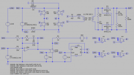
A simple tentative LTSpice model.
LINE is the AC mains, 340V peak to peak. REC turns it into a full wave rectified voltage. LBOOST is the boost inductor. M1-M4 is the bridge. RSNS in the return to REC effectively measures the boost/input line current as SNS.
SNS is fed to a current error amplifier, CEA. Compensation is standard slope matching. Demand signal DEM is set to follow the rectified line voltage, REC. This gives you the power factor correction. Ultimately that would involve voltage feedback and the other things commonly available in a PFC IC but for the moment it is set to give about 200W output.
Basic Bridge drive signals are non-overlapping O/N from the D-Type. The PWM signal via the OR gates under control of the CEA to force overlap and charge the boost inductor.
PRI/SEC are the main 1:1 transformer. Inductances are representative of magnetising inductance. Leakage inductance is included. Full bridge rectification on the secondary into the filter capacitor and load with a bit of snubbing.
D6 clamps overvoltage on the bridge switches that results from the leakage inductance. It is one of the sources of losses.
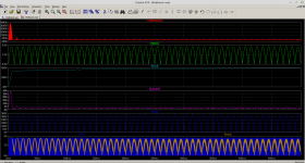
First picture is start up to 500mS. There is inrush current and that is common to what is found in a standard boost used for PFC. Some form of soft start might be required but if start up is timed/controlled it might be reasonable to look at device transient thermal impedances.
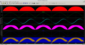
Second picture is after start up is over. It's not strictly in regulation but with bare PFC such as this you will get sinusoidal ripple at some level on the output and the loop bandwidth will be limited. With a Class A load it will be what it is. With a Class B load it will be higher.
As I have hinted before I get the impression that Valve Type People are not averse to having ripple on the supply and are happy to use LC iron filters to reduce it.
If you wish I can support you with up to £2000 development costs with payment timing details to work out but no financial strings beyond an initial it stops when we fall out and the loss is mine.
Let me know in this thread and we'll make the rest up as we go along in this thread.
...
TubesMan wants 420V-430V at about 200W so I thought I would miss that specification. They also mentioned the possibility of 90-270VAC and power factor corrected.
I shall bite my tongue...
A simple tentative LTSpice model.
LINE is the AC mains, 340V peak to peak. REC turns it into a full wave rectified voltage. LBOOST is the boost inductor. M1-M4 is the bridge. RSNS in the return to REC effectively measures the boost/input line current as SNS.
SNS is fed to a current error amplifier, CEA. Compensation is standard slope matching. Demand signal DEM is set to follow the rectified line voltage, REC. This gives you the power factor correction. Ultimately that would involve voltage feedback and the other things commonly available in a PFC IC but for the moment it is set to give about 200W output.
Basic Bridge drive signals are non-overlapping O/N from the D-Type. The PWM signal via the OR gates under control of the CEA to force overlap and charge the boost inductor.
PRI/SEC are the main 1:1 transformer. Inductances are representative of magnetising inductance. Leakage inductance is included. Full bridge rectification on the secondary into the filter capacitor and load with a bit of snubbing.
D6 clamps overvoltage on the bridge switches that results from the leakage inductance. It is one of the sources of losses.
First picture is start up to 500mS. There is inrush current and that is common to what is found in a standard boost used for PFC. Some form of soft start might be required but if start up is timed/controlled it might be reasonable to look at device transient thermal impedances.
Second picture is after start up is over. It's not strictly in regulation but with bare PFC such as this you will get sinusoidal ripple at some level on the output and the loop bandwidth will be limited. With a Class A load it will be what it is. With a Class B load it will be higher.
As I have hinted before I get the impression that Valve Type People are not averse to having ripple on the supply and are happy to use LC iron filters to reduce it.
If you wish I can support you with up to £2000 development costs with payment timing details to work out but no financial strings beyond an initial it stops when we fall out and the loss is mine.
Let me know in this thread and we'll make the rest up as we go along in this thread.
...
Attachments
Last edited:
I wonder how this one works in comparison?
High-power LLC switching power supply KT88 300B tube amp power supply L14-10 | eBay
High-power LLC switching power supply KT88 300B tube amp power supply L14-10 | eBay
I wonder how this one works in comparison?
High-power LLC switching power supply KT88 300B tube amp power supply L14-10 | eBay
It looks interesting, it is a bit expensive and some of the output voltages are of questionable value, But at least it a step in the right direction.
L14-10 | eBay[/url]
"Instantaneous power: 1000W (power generated during dynamic signal impact, less than 100 megaseconds)"
")
//
As I have hinted before I get the impression that Valve Type People are not averse to having ripple on the supply and are happy to use LC iron filters to reduce it. ...[/QUOTE said:I get the impression that "Valve Type People" like the warm fuzzy sound of IM and THD caused by sloppy power supplies.
I am not sure of what to make of your offer.
As I indicated in a previous post, I have some physical disabilities that limit my mobility.
This PS is intended to run a medium power stereo, or high power mono block design. I want to address component and subsystem failings in tube amps that have them mired in '50s sound quality. Or in the case of SE amps, the 1920's. Weight and hum feed through are one issue. Do you know how high is the shipping cost on a linear 300VA transformer to Manila? It is huge! More than the cost of the transformer.
I might be interested in doing small scale bespoke sale of the amp, but right now my goal is to get out from the debt I incurred from my sickness ( I'm American, I have no health insurance) by starting an online store selling other peoples stuff i.e. passive income. I need the HV SMPS design on paper to figure out parts cost, feasibility, and suppliers.
Mains powered SMPS are a challenge that often needs a bit of experimentation and a soft start approach.
It's far easier to make a low voltage primary.
I think you are right, but having two supplies defeats the whole purpose of the HV SMPS. I looked on Mouser for a 12-28V 200W switcher to drive a LV to HV switcher, the best I could find was $60. It didn't seem an elegant solution to the problem.
FWIW, I use a 12 ATX into 12V boost converters in a few of my tube amp designs...
This is good for preamp/phono/low power like EL84 or the like: 150W Inverter Boost Board Transformer DC-AC 12V to 110V 200V 220V 280V Converter 982878617651 | eBay
This is good for a more power amp like 100WPC: 500W 12VDC transfer 18VAC & 0-220v-380v inverter module | eBay
And you can make quite an amp with this one if you have enough balls at 12V: 1000W DC12V TO AC 0-50V-110V-220V-330V high frequency inverter variable DC TO AC | eBay
Koda.
I just got outclassed.
As much as Id like to be included I dont think my knowledge would be to any use at this point. All I can offer is PCB design then.
No you didn't. I might have more, unqualified, experience which means I can dream up silly topologies that may or may not work. I am already seeing some of the pitfalls in this one in terms of minimum load which may or may not be insurmountable.
It's not your knowledge. It's that you have made something that worked irrespective of how well it worked. Some of your design choices may have been questionable and some of the constraints you placed on yourself did not help.
You would be wise to question whether anything I might come up with would be any better. However I can give you the design reasoning and knowledge about the proposed topology such that you would understand it and be able to proceed with some confidence.
I would also expect us to be able to characterise the thing fully in LTSpice before committing to real circuit diagrams and a PCB layout and actually spending any money. I am not looking for someone to do an hourly rate for PCB layout for me. I'm not commercially minded. This is for DIY/Hobby interest, kind of open source if you wish.
Basically if you are interested it is your project and your time plus mine for free and, if we get to that stage, you knock up a BOM and an order list, I paypal you your costs plus a couple of beers you go and buy and build. Your budget limit to get to a final product is £2000. That's my sunk cost limit and I hope you/we can do it for less.
If you are interested then one thing that might break this is I would like it done using LibrePCB without relying on pre-supplied component models. That's a learning curve and extra work for you. That's me putting my management hat on and I hate myself already.
LibrePCB
I get the impression that "Valve Type People" like the warm fuzzy sound of IM and THD caused by sloppy power supplies.
I am not sure of what to make of your offer.
Cough sorry. I don't have much experience of Valve equipment. You have already suggested linear post regulation and assuming the 4V ripple at about 400V with 0.5A out then it can be a thing.
The offer is more or less as above. If they are happy then Caterpilar gets to do the hard work I give design input and pay for the bits and if you and they wish to commercialise it then that's up to you. It will work but it might not be the lowest cost solution.
As I suggest I'd prefer to keep it open source with the details in this thread.
Last edited:
Only thing I don't like is the 20kHz switching frequency. That is too close to audio for my comfort, I'd like 50kHz or more. And I'd use something other than a computer PS to run it. But this is the direction I am looking at.
Change a couple of resistors/caps and you change the switching frequency. The lase two use an SG3525. https://www.onsemi.com/pub/Collateral/SG3525A-D.PDF
The first one switches at about 37kHz... The other two are at 20kHz, but I see no 20kHz on the tubes...
Last edited:
I agree that cat is underestimating his abilities. At this point what I think best, is to let "real" engineers take it from 90-240Vac down to 12-24Vdc, then I/we do LVDC to HVDC at around 100kHz. That part is much simpler. I'm looking now for an AC to DC converter at the best voltage/current/transformer compromise.
The best description of valve people can be gotten from the fact that SOME of them will pay $1000+ for an amp using a tube made in the 1930's and will only put out <5W at 10% distortion, and marvel at the"rich full palpable sound stage". Not all are like that, many(most?) believe in fidelity.
The best description of valve people can be gotten from the fact that SOME of them will pay $1000+ for an amp using a tube made in the 1930's and will only put out <5W at 10% distortion, and marvel at the"rich full palpable sound stage". Not all are like that, many(most?) believe in fidelity.
Change a couple of resistors/caps and you change the switching frequency. The lase two use an SG3525. https://www.onsemi.com/pub/Collateral/SG3525A-D.PDF
The first one switches at about 37kHz... The other two are at 20kHz, but I see no 20kHz on the tubes...
Yeah, that is the chip I think is best. But, change the freq then you need to change the transformer.
Have you done an IM or FFT test? If so, do you seen PS residual noise?
I agree that cat is underestimating his abilities. At this point what I think best, is to let "real" engineers take it from 90-240Vac down to 12-24Vdc, then I/we do LVDC to HVDC at around 100kHz.
Humph... I'll have you know. OK not so much of that but in the past I have designed commercial low noise off line bench power supplies up to 500W which did not become commercial. I used the word unqualified in the sense that as far as you might be concerned my cat might have randomly typed this reply whilst washing his bum on my keyboard.
Proof of pudding is what I might supply in terms how the thread, if I rob it, develops in technical terms. I don't expect any commitment unless things make sense.
The suggested supply does it all in one. Power Factor Corrected Off Line to 400V or whatever HV within reason that you might specify. Because it is current fed you can get additional outputs, including filament supplies, by simply adding additional windings to the transformer and, assuming tight coupling, they will track each other.
- Home
- Amplifiers
- Power Supplies
- Powerful SMPS for tube ampifier