Hi there,
This little circuit has been designed to replicate a test screwdriver, in a better and more modern version (it also has the the complexity of a gas plant compared to the original, but that is part of the fun!).
A test screwdriver is based on a small neon bulb in series with a large resistor. It can visualize small stray currents caused by AC voltages >~60V.
It is a rather antique device, yet it is quite effective (I mean in its operation, I am not going to discuss its usefulness, or lack thereof): a neon bulb is quite effective in converting electrical into luminous power.
Modern LEDs are better though, but they suffer from a severe handicap: a neon typically drops 60 to 65V, when the forward voltage of a LED under low current conditions is only 1/20th to 1/45 of that.
This means that when a LED is a subjected to the same current as a neon, it will receive a mere 3% of the power.
The remedy is to use a circuit that converts the excess voltage into current, instead of wasting it in an impedance: in short, a current multiplier.
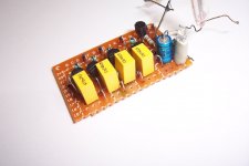
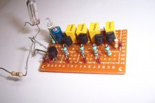
This harvester is a 4-stage current multiplier, capable of operating at the µA level if necessary.
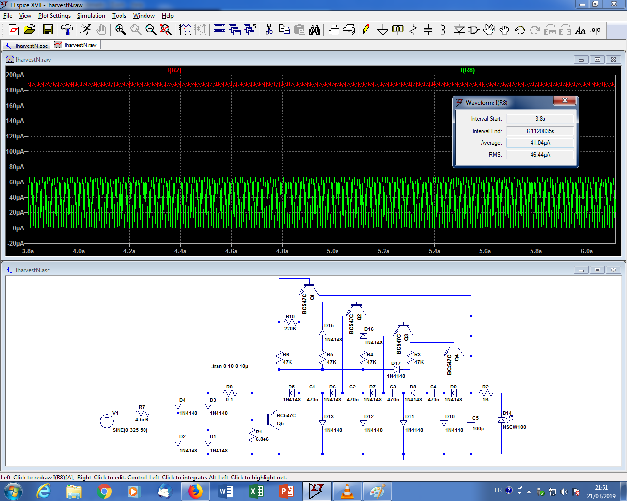
The principle is to charge 4 capacitors (C1 to C4) in series, and to discharge them in parallel into the load.
The switches are a mix of passive (or autonomous) ones: diodes, and active (or controlled) ones: transistors.
A voltage multiplier doesn't require active switches: it can content itself with diodes.
Why would a current multiplier be different? After all, the duality between voltage and current, resistance and conductance, etc. should also allow the use of passive switches, but the duality principle also demands that capacitors are exchanged for inductors, which would be highly unpractical for µA currents, 50 or 60Hz frequencies and volt or tens of volt levels.
For these reasons, a number of the necessary switches are transistors (Q1 to Q4).
Ordinary voltage or current multipliers normally operate on AC waveforms. This circuit has an originality: it can operate on pulsed DC.
The distinction might seem purely academic, but it has a huge importance: with AC, the average current is halved compared to pulsed-DC: with DC, the 50 or 60Hz input can first be fullwave-rectified before it is processed, thus doubling the available average current.
This means that the 4-stage version shown here is in in fact equivalent to an 8 eight-stage one, and even to a 10 stage, thanks to an additional trick: the charging current is also recycled into the load.
The actual multiplication ratio is in fact comprised between 9 and 10, about 9.5, because of the non-unity duty cycle, and because of the losses caused by the transistors base currents.
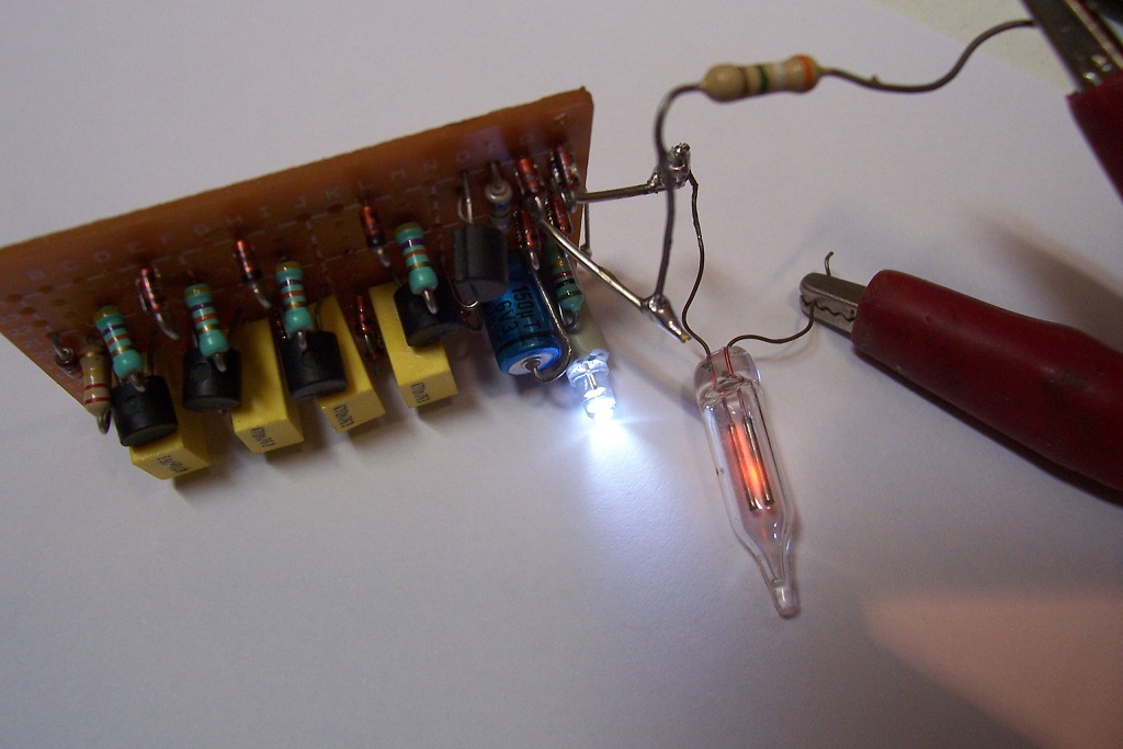
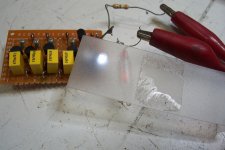
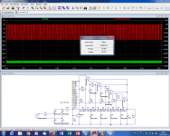
The gain is very sizeable though, as this pic shows: the neon and the harvester are connected in series and see exactly the same current, around 40µA in this case.
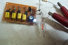
The DC output current is approximately 190µA.
This is sufficient to correctly light a modern LED, as the pics show, but also to serve as a supply for electronic circuits: nowadays, 190µA at 3.3V, 5V, 12V or more is plenty enough to do lots of things.


The supply source can be the leakage current current between the 0V of a class II device and earth, or even between the 0V's of two class II devices.
This example has been optimized to harvest currents from 10 to 100µA at 50 or 60Hz, but any scaling is possible, by adapting the component values.
Have fun!
This little circuit has been designed to replicate a test screwdriver, in a better and more modern version (it also has the the complexity of a gas plant compared to the original, but that is part of the fun!).
A test screwdriver is based on a small neon bulb in series with a large resistor. It can visualize small stray currents caused by AC voltages >~60V.
It is a rather antique device, yet it is quite effective (I mean in its operation, I am not going to discuss its usefulness, or lack thereof): a neon bulb is quite effective in converting electrical into luminous power.
Modern LEDs are better though, but they suffer from a severe handicap: a neon typically drops 60 to 65V, when the forward voltage of a LED under low current conditions is only 1/20th to 1/45 of that.
This means that when a LED is a subjected to the same current as a neon, it will receive a mere 3% of the power.
The remedy is to use a circuit that converts the excess voltage into current, instead of wasting it in an impedance: in short, a current multiplier.
This harvester is a 4-stage current multiplier, capable of operating at the µA level if necessary.
The principle is to charge 4 capacitors (C1 to C4) in series, and to discharge them in parallel into the load.
The switches are a mix of passive (or autonomous) ones: diodes, and active (or controlled) ones: transistors.
A voltage multiplier doesn't require active switches: it can content itself with diodes.
Why would a current multiplier be different? After all, the duality between voltage and current, resistance and conductance, etc. should also allow the use of passive switches, but the duality principle also demands that capacitors are exchanged for inductors, which would be highly unpractical for µA currents, 50 or 60Hz frequencies and volt or tens of volt levels.
For these reasons, a number of the necessary switches are transistors (Q1 to Q4).
Ordinary voltage or current multipliers normally operate on AC waveforms. This circuit has an originality: it can operate on pulsed DC.
The distinction might seem purely academic, but it has a huge importance: with AC, the average current is halved compared to pulsed-DC: with DC, the 50 or 60Hz input can first be fullwave-rectified before it is processed, thus doubling the available average current.
This means that the 4-stage version shown here is in in fact equivalent to an 8 eight-stage one, and even to a 10 stage, thanks to an additional trick: the charging current is also recycled into the load.
The actual multiplication ratio is in fact comprised between 9 and 10, about 9.5, because of the non-unity duty cycle, and because of the losses caused by the transistors base currents.
The gain is very sizeable though, as this pic shows: the neon and the harvester are connected in series and see exactly the same current, around 40µA in this case.
The DC output current is approximately 190µA.
This is sufficient to correctly light a modern LED, as the pics show, but also to serve as a supply for electronic circuits: nowadays, 190µA at 3.3V, 5V, 12V or more is plenty enough to do lots of things.
The supply source can be the leakage current current between the 0V of a class II device and earth, or even between the 0V's of two class II devices.
This example has been optimized to harvest currents from 10 to 100µA at 50 or 60Hz, but any scaling is possible, by adapting the component values.
Have fun!
Attachments

Last edited:
") . Mind you not sure if I have used mine as other than a screwdriver this century!
. Mind you not sure if I have used mine as other than a screwdriver this century!Yes... in principle.Neon will work on steady DC.
Taking the nitpicking a step further, when an AC voltage/current lights the neon of test screwdriver, it is in the vast majority of the cases thanks to capacitive coupling: nowadays, shoes are insulating, floors are insulating, even socks are insulating.
This means that in practice, even a neon-based tester will generally fail to detect DC, except when an explicit ohmic path to the earth is provided, by standing bare-footed, or pressing a hand against a masonry wall for example.
That said, I do not particularly recommend using a test screwdriver as a deterministic tool, and this thread is mostly about harvesting minute currents, as the title indicates.
The circuit could emulate a test screwdriver in most situations (in combination with a large series resistor), but is not particularly practical or advantageous as all the components would need to be stuffed inside a screwdriver.
Possible variations, remarks:
The circuit can operate for a reasonable range of currents, but to improve the conversion efficiency, the resistor values should be scaled according to the expected input current, otherwise conduction losses or no-load losses will increase.
The capacitor values should also be scaled.
This example has 4 stages, but this can easily be altered in both directions, obviously.
The input voltage will be the output voltage + losses multiplied by the number of stages. With this example, it is around 30V.
The zero-crossing buffer Q5 is not strictly necessary, but without it the shunt resistor R1 would need to be much lower, increasing the no-load consumption.
Other types of semiconductors like FETs could be used as switches, to eliminate the need for base currents, but the discharge phase is very short and requires a relatively large peak current, meaning jFETs would not be practical.
MOSFETs should be usable, if they have a low enough threshold voltage.
R1 needs to be smaller than the optimum simulation value (15MΩ), because the base node is extremely sensitive to stray capacitive couplings.
This could be problematic if the circuit is scaled for much lower input currents.
What could the possible uses of such a harvester be?
Here is an idea: if you are lucky enough to have a HV power line in the vicinity (!), you could probably collect the electrostatic field it generates with an aerial or a large plate: if it works with fluorescent tubes, it probably also works with this circuit...
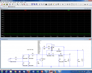
Here is another (boring) application for this circuit: a high-current voltage divider/current multiplier.
Such a circuit can have many uses, especially for DIYers, where a salvaged transformer has an excessive voltage, or a single winding: it can reduce the voltage from a transformer, or it can generate multiple voltages from a single winding, without the losses associated with linear regulators or the noise and complexity of switching ones.
This example delivers 36V DC from a 140V AC source (200V^).
The input power is 14.56W, for 13W out, an efficiency of 89%.
This is not exceptional, but the diodes are ordinary ones, and the capacitors are minimal.
With schottky's for D5 to D13, this could be improved.
Attachments
Indeed.
Here is an illustration of what I said above: here, the multiplier is configured for 2, thus 0.5 for voltage.
It solves a very common problem: create a split supply from a single one (note that there are some caveats, but keeping them in mind, it would be perfectly usable)
Here is an illustration of what I said above: here, the multiplier is configured for 2, thus 0.5 for voltage.
It solves a very common problem: create a split supply from a single one (note that there are some caveats, but keeping them in mind, it would be perfectly usable)
Attachments
BTW, I forgot to mention a feature common to all of these multipliers: since they operate on the fullwave rectified waveform, their ripple frequency is double that, 200 or 240Hz.
Depending on the order and the implementation, some of the base 100Hz can also leak out and modulate the 200Hz ripple, because of non-equivalent diode drops, etc.
Depending on the order and the implementation, some of the base 100Hz can also leak out and modulate the 200Hz ripple, because of non-equivalent diode drops, etc.
- Status
- This old topic is closed. If you want to reopen this topic, contact a moderator using the "Report Post" button.
- Home
- Amplifiers
- Power Supplies
- Kind of useless, but fun: a stray currents harvester