Hi, I'm new to this forum and I have a little problem to solve.
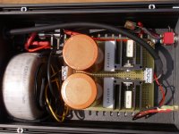
i have this dual psu + and - 12v.
Now i must to change for + and - 15v.
There is something wrong of my PSU?
forgive me if I don't put the scheme, I did not do it, I should disassemble it all to see under the tracks, however if it is necessary, I will do it.
if possible I would like to improve it.
What do you recommended to use?
is an psu for electronic crossover,
absorption about 200mA.
Attachments
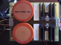
Provided you have sufficient raw DC voltage across the large reservoir caps (and the ripple component of that DC mustn't dip below 18 volts) then I would assume you could just swap the 7812 and 7912 devices for the 15 volt equivalents.
The raw DC voltage available is the really important factor though.
The small 0.1uF cap will be either on the input or on the output of the reg which leaves the question of one or the other not being decoupled. You should really have a small 10uF electrolytic decoupling each to ground.
The raw DC voltage available is the really important factor though.
The small 0.1uF cap will be either on the input or on the output of the reg which leaves the question of one or the other not being decoupled. You should really have a small 10uF electrolytic decoupling each to ground.
With your voltmeter, measure (AC) the voltage between the two yellow secondary wires. Then we can tell you if you have sufficient transformer voltage. You may be able to read the transformer secondary voltages on the transformer. I believe I read "30 V.A." but I cannot see the secondary voltages.
Mooly
is the 10uF electrolytic polarized or not?
Decoupling between?
I put it between the earth and?
You should really have a small 10uF electrolytic decoupling each to ground.
is the 10uF electrolytic polarized or not?
Decoupling between?
I put it between the earth and?
Secondary transformer, it is written 18 -0- 18.
You can do +/-15Vdc.
As I understand Mooly, the 10uF go at the outputs. For the positive part, "-" to ground and "+" to the positive rail.
For the negative part, "+" to ground and "-" to the negative rail. Yes, the two 10uF are polarized.
Last edited:
Secondary transformer, it is written 18 -0- 18.
That should be fine and would give about 25 volts raw DC.
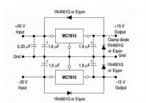
The caps are not very critical but should be close to the regulator pins. Everyone has their own ideas on decoupling and so its only fair to point out that one of the data sheet recommends in the region of 0.33uF on the input and 0.1uF on the output for a 7815 and an 'unspecified' electrolytic on input and output for the 7915.
Fit 10uF and you wont go far wrong.
It might also be prudent to fit inverse diodes across the outputs of each and also across each regulator. Use 1N4004 type or similar. This prevents possible latchup of the regulators which is a widely recognised issue although I've not really come across the problem myself.
Attachments
The caps are not very critical but should be close to the regulator pins. Everyone has their own ideas on decoupling and so its only fair to point out that one of the data sheet recommends in the region of 0.33uF on the input and 0.1uF on the output for a 7815 and an 'unspecified' electrolytic on input and output for the 7915.
Fit 10uF and you wont go far wrong.
It might also be prudent to fit inverse diodes across the outputs of each and also across each regulator. Use 1N4004 type or similar. This prevents possible latchup of the regulators which is a widely recognised issue although I've not really come across the problem myself.
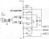
Something similar is at the input to the crossover.
Attachments
OK... hmmm what shall I say ")
You see, the whole point of a regulator like the 7815 or 7915 is to maintain a tight grip on the output voltage, and that network of coils, series diodes and massive caps totally destroy that.
The regulator can not now change its output voltage in relation to current demands quickly enough because of the big cap. So big caps aren't always a great idea.
The diodes provide do provide polarity protection for the load (if you were to wire it up incorrectly).
So .. change my circuit to your example, it can be done, there is space,
and skip the crossover input circuit, ok.
thank you all
If it works correctly, I see two answers, the first electrically, the circuit works, yes.
The second, from the point of view of quality, is what I also wonder, technically I see a circuit with few components and I would think that it is a basic circuit?
But sometimes someone praises the performance of simple circuits with few components.
I have no idea what improvements I could make with other circuits, as long as I can't listen.
Can you show me what the alternatives could be in a hypothetical quality scale, if it exists, starting from the simplest circuit to the most complicated and / or performing one?
You can make circuits as complicated and involved as you want, the question is what does it achieve in relation to your own design goals. More complex isn't always better.
A simple shunt regulator consisting of a resistor, a Zener and a cap could easily outperform a poorly implemented 78/79 set up at low currents (such as supplying a few opamps).
A simple shunt regulator consisting of a resistor, a Zener and a cap could easily outperform a poorly implemented 78/79 set up at low currents (such as supplying a few opamps).
I spent these days seeing what other circuits are available.
I've been looking for what's better, as superregulators and shunts, I'd like to do something better than what I have now.
And a thought has made its way, instead of modifying my power supply,
maybe it's better to make a new one, for at least 2 reasons.
The first is that I can compare the new psu with the old one, and take away any doubts and compare them whenever I want ... comparisons with memory are not a good way to establish a value judgment.
The second, the changes necessary for the new type of circuit may not be compatible with the current circuit,
if the changes are too many, it's better to do it all over again.
Moreover now the power supply is connected to the crossover via a 60cm cable, instead the new power supply could be made modular, that is, the regulation circuits placed inside the crossover, there is some space, I can evaluate ..
If I could not put it in and / or even for reasons of necessary cooling, I could still think of putting it as close as possible and moving away only the transformer connected with a cable.
It should be better to have the adjustment circuits close to the crossover circuit.
Then,
for the design of the new regulator power supply
Is there anything else I should consider to optimize?
- Status
- This old topic is closed. If you want to reopen this topic, contact a moderator using the "Report Post" button.
- Home
- Amplifiers
- Power Supplies
- There is something wrong with my PSU?