Hello.
I'm currently restoring an old tube amplifier and I would like to add a bleeder resistor to the PSU for safety reasons.
I was wondering where specifically one have to insert the bleeder resistor (R3) in the PSU circuit pursuing efficiency and effectiveness (please consider the attached design). Is across the last capacitor right? Or should it be across one of the previous capacitors?
Moreover is the following procedure (posted in another thread) correct in order to define wattage and resistance needed?
Thank you all.
I'm currently restoring an old tube amplifier and I would like to add a bleeder resistor to the PSU for safety reasons.
I was wondering where specifically one have to insert the bleeder resistor (R3) in the PSU circuit pursuing efficiency and effectiveness (please consider the attached design). Is across the last capacitor right? Or should it be across one of the previous capacitors?
Moreover is the following procedure (posted in another thread) correct in order to define wattage and resistance needed?
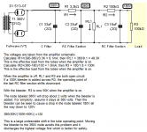
T=RC , T= 5 minutes * 60 seconds = 300 seconds, C= 40000uF = .04F.
300/.04 = R = 7500 ohms. Power dissipation = E^2/R = 30^2/7500 = .12W
If you use a 7.5K ½ W resistor it will discharge your 40000uF of capacitors in 5 minutes.
Yes, just one resistor across the leads going to the amp.
Thank you all.
Attachments
Is R2 really 100K? Seems quite high but if it is 100K then R3 placed as in your diagram cuts the voltage across C3 in half. Place the bleeder in parallel with C1. You didn't specify a discharge time but I would just use 1 megOhm to get a discharge time of a minute or two. A 1 Watt resistor will do.
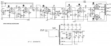
Thanks for the reply. Yes it is 100k. Please see the attachment. The amplifier I'm working on is a modified Heathkit A7-E. Regarding the bleeder resistor, some folks say across the last capacitor other say across the first one, so why you suggest to put it across the first one?
Attachments
")
Some designs can use a bleeder 'at the end' to constrain capacitor voltage ratings 'towards the end', especially if the output stage uses more than about 450V, and the driver/preamp stages are derived from a dropper daisy chain of RC sections. Placing the bleeder at the output stage end can expose preamp stage caps to higher voltage if the tubes are pulled during testing.
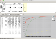
In the OP's PSUD example, the supply B+ is over 450V, and may well be made from a series connection of caps, each with its own balancing resistor - that also acts as a bleed resistor for all the amp.
You can use PSUD2 to identify the power dissipation in a bleed resistor - it can be derived from the PSUD2 rms current data column through the resistor (but based on a steady state region of PSUD2 - eg. use 1-2 seconds of reporting delay.
Last edited:
Some designs can use a bleeder 'at the end' to constrain capacitor voltage ratings 'towards the end', especially if the output stage uses more than about 450V, and the driver/preamp stages are derived from a dropper daisy chain of RC sections. Placing the bleeder at the output stage end can expose preamp stage caps to higher voltage if the tubes are pulled during testing.
In the OP's PSUD example, the supply B+ is over 450V, and may well be made from a series connection of caps, each with its own balancing resistor - that also acts as a bleed resistor for all the amp.
You can use PSUD2 to identify the power dissipation in a bleed resistor - it can be derived from the PSUD2 rms current data column through the resistor (but based on a steady state region of PSUD2 - eg. use 1-2 seconds of reporting delay.
Placing the bleeder at the end is ok if the amplifier was designed for it. In this case there is no bleeder so adding one at the end greatly shifts the first tube operating point.
The PSUD example is inaccurate since it does not model the power supply loading from the tubes. The schematic shows 390V as the output stage B+.
Bleed resistor power is primarily a DC issue and can be calculated from Ohm's Law. High precision is not needed.
I would put 1 meg across C1 as stated in my previous message. Mouser part number 279-ROX1SJ1M0 would be suitable.
Attachments
Restoration often involves replacing power supply electrolytics. Sometimes that can require replacing caps with 500V to 600V peak style ratings, which are now not available. Sometimes a single cap can has multiple caps, and that style of can is now not available, or the restorer is aiming to improve hum and use discrete caps to allow local stage star point grounding.
Some are cautious about start up delay in stage loading compared to rectifier tube conduction timing (even indirectly heated types), when all caps in the amp can be exposed to unloaded power supply voltage.
All issues discussed are worthwhile appreciating by the OP.
Some are cautious about start up delay in stage loading compared to rectifier tube conduction timing (even indirectly heated types), when all caps in the amp can be exposed to unloaded power supply voltage.
All issues discussed are worthwhile appreciating by the OP.
[...]
In the OP's PSUD example, the supply B+ is over 450V, and may well be made from a series connection of caps, each with its own balancing resistor - that also acts as a bleed resistor for all the amp.
[...]
Thank you for the clarification. So would you add another bleeder resistor across C1 or not?
Placing the bleeder at the end is ok if the amplifier was designed for it. In this case there is no bleeder so adding one at the end greatly shifts the first tube operating point.
The PSUD example is inaccurate since it does not model the power supply loading from the tubes. The schematic shows 390V as the output stage B+.
Bleed resistor power is primarily a DC issue and can be calculated from Ohm's Law. High precision is not needed.
I would put 1 meg across C1 as stated in my previous message. Mouser part number 279-ROX1SJ1M0 would be suitable.
Thank you very much! Searching through threads in this forum related to bleeding resistors was not clear to me why sometimes one suggested to insert it across the end and sometimes across the beginning of all the capacitors.
Restoration often involves replacing power supply electrolytics. [...]
I'm intended to do so. I also have to double check voltage across each old capacitor. I already measured the voltage i.e on the first capacitor resulting in 455V and I thinking to replace it with a new one rated for 475V but the original are rated for 500V/550V so I'm not sure...
Last edited:
I'm intended to do so. I also have to double check voltage across each old capacitor. I already measured the voltage i.e on the first capacitor resulting in 455V and I thinking to replace it with a new one rated for 475V but the original are rated for 500V/550V so I'm not sure...
Bit off topic, but I remeasured and voltages across C1, C2, C3 of the original amp I'm going to restore and they are respectively 435V, 431V, 264V.
As I said the amp use 6 volt tubes rather than 12 volt ones but did I measured the voltages across the capacitors correctly considering that the only tube I left in place was the rectifier?
Why was it 475V a few days ago but 435V today?
Since standard caps go to 450V, this is critical; also you should be getting near-same numbers every time you measure the same thing. ("Measure once, cut twice.")
Regarding the answer to your first question that's because I recalled wrong when I written 455V (435V, 431V, 264V is most probably what I measured the first time too). Secondly, the uploaded schematic is the original one and being so it does not illustrate completely the components in the amplifier I'm working on (I already checked each component and regarding the PSU and tubes they are completely different from the schematic).
NB; 475V is the voltage value of the new capacitors I bought to replace the old ones as specified in my previous post.
Last edited:
- Status
- This old topic is closed. If you want to reopen this topic, contact a moderator using the "Report Post" button.
- Home
- Amplifiers
- Power Supplies
- Bleeder resistor positioning and dimensions.