I only have a 6AX4GT datasheet to quickly look at, but the "DC plate current" rating of 125mA is for "Damper service". Do you have a datasheet that provides a rating for a power supply rectifier role?
The other datasheet rating that is imho better to use is the 'steady state peak current', which can be compared to predicted peak current level in a PSUD2 simulated circuit of your intended power supply.
The other datasheet rating that is imho better to use is the 'steady state peak current', which can be compared to predicted peak current level in a PSUD2 simulated circuit of your intended power supply.
Thanks. As I said, ignoring any derating for damping...it's the concept I'm after, not the actual numbers.
Basically, my question is if a single diode (any tube diode) is rated at some current level (e.g. 137 for the 6AX4GT - The Sylvania sheet says 125mA but the other GT sheets say 137 - but any tube diode will do) is that the current rating whether run as a single tube in half wave rectification or two tubes in full wave?
At this point, though, I'm thinking the answer is yes, it's the same (not doubled just because two tubes are used). Each one passes the relevant portion of the sine wave at up to it's rated max.
I suggest that you stick with the datasheet ratings that are applicable to the application.
The damper diode datasheet only has a peak diode current rating that is possibly applicable to power supply circuit use. If it is applicable, then it can operate at that continuous peak level whether it is one diode in a half-wave rectifier, or as one of two diodes in a full-wave. Imho, it is not appropriate to point to another rating that has no association with power supply use and try and deduce what it means for power supplies.
As the continuous peak rating is not the same as the dc output current from a rectifier and filter circuit, you can use Schade or a number of text-book references to estimate what dc output current will be achieved by a particular type of rectifier and filter, given a peak diode current spec. Or even easier - use PSUD2.
Last edited:
use 872s and don't even think about it.
Actually, I won't have mercury tubes in the house (mercury vapor in a hot thin glass envelope doesn't seem like a great idea to me - vapor inhalation can be serious whereas swallowing elemental mercury isn't...isn't AS serious).
Very little, and I'm trying to move away from them. But there's a tradeoff. Flourescent lighting uses MUCH less energy, which displaces the mercury discharged by power plants. So while our exposure risk is relatively higher than having none in-home, the broader benefit to the environment is also higher. Broad access to LED lighting has made our shift away from Fluorescent lighting easier and quicker.
My understanding, though it's hard to determine accurately, is that MV rectifiers like the 866 and 872 contain a LOT more mercury than fluorescent lights (~4mg in a CFL). And they burn hotter, which suggests a bigger problem with dispersion of mercury vapor and subsequent inhalation (which is the bigger problem than room-temp liquid mercury). Here's a quote from another thread that sums up my concerns:
AND, I've read that they are generally very noisy rectifiers (though haven't heard or measured them).
In short, I just don't see the value given the risk, and the comparison is apples to oranges anyway.
My understanding, though it's hard to determine accurately, is that MV rectifiers like the 866 and 872 contain a LOT more mercury than fluorescent lights (~4mg in a CFL). And they burn hotter, which suggests a bigger problem with dispersion of mercury vapor and subsequent inhalation (which is the bigger problem than room-temp liquid mercury). Here's a quote from another thread that sums up my concerns:
there's an important difference between breaking an MV rectifier or a Hg thermometer... In the former case, the Hg is vaporized! It would spread around the room in litterally seconds. People would need to hold their breath and clear the house immediately and then wait outside for hours or days until all the vapor has deposited on surfaces (which then need to be cleaned ). In the latter case, the droplets can just be collected on a piece of paper and discarded. Liquid mercury would only release some vapor when left lying on the floor for weeks. Remember you could drink a thermometer and not get poisoned; the vapour reaching the lungs is where poisoning takes place.
AND, I've read that they are generally very noisy rectifiers (though haven't heard or measured them).
In short, I just don't see the value given the risk, and the comparison is apples to oranges anyway.
This datasheet says 165mA DC and 1000mA peak, clearly.
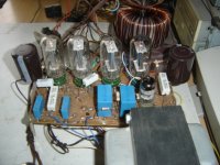
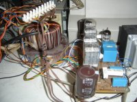
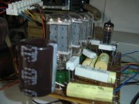
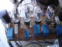
Using it to drain 165mA is safe for them. As the current is splitted between the two in a fullwave rectifier, then you can double it. I am building an amplifier with 4 compactron 6AX3-6BE3 damper diodes in bridge, but I prefer choke input filter, which allow me to use as much output cap as 680µF.
Using it to drain 165mA is safe for them. As the current is splitted between the two in a fullwave rectifier, then you can double it. I am building an amplifier with 4 compactron 6AX3-6BE3 damper diodes in bridge, but I prefer choke input filter, which allow me to use as much output cap as 680µF.
Attachments
Last edited:
This datasheet says 165mA DC and 1000mA peak, clearly.
Using it to drain 165mA is safe for them. As the current is splitted between the two in a fullwave rectifier, then you can double it.
Well, that's the gist of my question. If one can support 165mA but it's only providing half of the wave form, and I use another to supply the other half of the waveform, it seems each "bump" in the voltage wave can handle up to 165mA, but because they are not going at the same time, it still seems like the total current with two in full wave is 165mA, not double.
The datasheet clearly says that is for 'TV DAMPER SERVICE' - so a leap of faith is needed to apply that to mains frequency rectifier service, or a good understanding of what the different services mean to the operating conditions of the diode.This datasheet says 165mA DC and 1000mA peak, clearly.
It seems to to had read in the Radiotron, that specifications for double diodes are for only one of them, so specs are to be doubled for full wave rectifiers.
Damper services for a diode means that the diode conducts about half horizontal cycle of 64µS for 15625 lines as here, from the left side of the CRT face to the center, recirculating the current injected to the LCR system composed by flyback transformer, yoke, UHT supply, (linearity and width coils if any), vertical ramp oscillator/generator; and in the color receivers, the convergence mechanisms. The waveform of current is a ramp down from the almost same current that the output pentode injected in the system less the looses in the circuit, down to zero mA. In the later designs, currents was not the same, but scaled by the horizontal output transformer (Flyback transformer). I don't remember now if scaled down or up.
In the other hand, having a rectifier with capacitor input to the filter, the peak is a short pulse of high current, to recharge the capacitance of the filter, slightly flat topped by the leakage inductances and resistances of the transformer's secondary, and the primary parameters transferred to the HV secondary. So, although the service is not the same, they are not too different. In fact, in the earlier TV sets, diodes for rectifier services without high cathode-filament isolation were used, with a separate and dedicated power transformer's heater winding.
- Status
- This old topic is closed. If you want to reopen this topic, contact a moderator using the "Report Post" button.
- Home
- Amplifiers
- Power Supplies
- Understanding tube rectifier current specs