I know this has been discussed to death, but I still have a few questions that I haven't seen a ton of discussion about. A few people have asked on the EEVblog forum, and the "design" threads turned into toxic flame wars.
I'm at that point when my Eico 1030 power supply is not really cutting it. For one, it needs some work. It should go to 400 volts, but it really only goes to 350 (weak tubes maybe?), and it's physically bigger than I'd like.
I have a nice beefy Tek 120-037 power transformer that I'm considering, otherwise I'll dig something else up. Ideally this project would use up some crap.
My real question comes in with regulation. For space reasons, I don't want to use tubes (unless there is a very, very good reason to do so). I'm planning to use a couple of power MOSFETS. I think the IRFPG50 will be suitable. If anyone has a better device for this that costs less, I'd love to hear about it.
My initial plan was to use a Maida style regulator, but then I found This neat little device on Mouser. The Maida style regulator seems a lot more popular than the LR8, and I'm wondering if it has a clear advantage. I do like the simplicity of the LR8, and I've heard about a lot of stability issues with Maida regulators.
Also, I'd like to come up with a decent way to avoid sending the MOSFET die in to low-earth orbit if the output is shorted. If a device under test shorts out, I'd prefer the power supply didn't dump the whole 500 volts into the mess. Anybody have a good suggestion for this? I'd like the power supply to handle 300-500 mA, with a safety margin. Would a simple LM317 set up as a 750mA constant current source (more than the power supply is designed for) be suitable for this?
I don't have a whole lot of confidence in this idea, as I feel like in the shorted output scenario I mentioned above it would blow before the MOSFETs do. If my math is right it'd be dissipating a few hundred watts in the worst case scenario.
If you do not use a foldback limitation (which I agree, is an annoyance (could we say limitation?) for a lab supply) or an input voltage switching scheme, your math is right, of course, but it is anyway preferable to design the supply to handle that kind of dissipation, even if it is short term.
The Elektria concept (see my signature) is a good tradeoff between raw performance, simplicity and reliability, because it does not use IC's in the HV current path (and it can be made completely discrete without difficulty).
It can also use an integrated reference, an integrated current regulator, etc
I have also described more "exotic" HV supply concepts (you can search the forum if you want to explore them), and all actually work: I still use them when I need to, but for a good no-frills, safe, all-purpose supply, Elektria is the way to go. It has a number of additional benefits, like being LDO, etc
Also, I'd like to come up with a decent way to avoid sending the MOSFET die in to low-earth orbit if the output is shorted. If a device under test shorts out, I'd prefer the power supply didn't dump the whole 500 volts into the mess. Anybody have a good suggestion for this? I'd like the power supply to handle 300-500 mA, with a safety margin. Would a simple LM317 set up as a 750mA constant current source (more than the power supply is designed for) be suitable for this?
An adjustable Maida-style bench supply that supports that much current and voltage output can be done, but it's not exactly trivial.
The problem using power mosfets or power BJTs in a linear style regulator is they are not made to withstand the conditions that a basic linear supply of your specifications would place on them. If you want to lower your max output current to say 100 mA, and lower your max output voltage to say 300V, then yes, I believe power mosfets or BJTs will work. That's been my personal experience anyway.
But supporting 500 mA at 0V to 450V output, and with the ability to withstand short circuit? No, not in my experience will any silicon device support that straight up in a simple linear supply, even heavily heat sunk, without logic circuitry to do some sort of current and/or voltage foldback.
In my case I wanted a very simple adjustable linear supply (no foldback). I settled on a solution after much trial and error of using power tubes as the predrop devices in the Maida topology. Current limiting was done through the screens themselves. You don't get adjustable current limiting with this approach (unless you add a variable screen voltage supply), but you do get max current limiting. It works well, although not precise down to the milliamp. It's intended for supply survival in the event of short circuit.
I used 6550 power tubes for the predrop devices. Screen is regulated at about 120V, with raw B+ at at constant 550V. The predrop devices drop all but about the last 20V of the requested output voltage, where the 317 does the final regulation a-la the Maida style. In the end mine supports 10V to 470V adjustable output, at up to 300 mA before entering current limit mode. It required 3x 6550 power tubes to achieve that.
Mine is not laboratory grade, but it works for what I need it to do. Why did I design/build one from scratch instead of just purchasing one over the counter? It was cheaper for one thing to build my own, and it was a great learning experience.
I'd be happy to show you more details about what I did, if you are really serious about building something like this. But again, it wasn't exactly trivial, even with my design goal of building a "simple" no-frills linear bench supply.
Last edited:
BJT's and MOSfets are two very different breeds of cat: beyond 100V or so, the SOA of BJT's shrinks to almost insignificant values, and it is extremely difficult to dissipate any amount of power, unless you parallel a large number of (preferably) specially selected devices. By contrast,The SOA of MOSfets follows almost the ideal contour, limited by dissipation, max current and max voltage. A difficulty is to stay within the allowed range for dynamic conditions, and for a lab supply these conditions can be quite demanding. This is why, even when I use an opamp-based limiting scheme I also keep the direct, transistor-based limiter to act as a feedforward path. Ths is essential for HV supplies. Using a common-source rather than a follower scheme is also helpful, because the common-source is natively a CCS, driven by the regulator to act as a follower.The problem using power mosfets or power BJTs in a linear style regulator is they are not made to withstand the conditions that a basic linear supply of your specifications would place on them. If you want to lower your max output current to say 100 mA, and lower your max output voltage to say 300V, then yes, I believe power mosfets or BJTs will work. That's been my personal experience anyway.
Once the dynamic behavior is OK, the rest is a matter of cooling: big sinks, paralleled devices, fans, etc.But supporting 500 mA at 0V to 450V output, and with the ability to withstand short circuit? No, not in my experience will any silicon device support that straight up in a simple linear supply, even heavily heat sunk, without logic circuitry to do some sort of current and/or voltage foldback.
In general, I design my supplies to survive ~10 minutes on a dead short at the max current, and include an overtemperature cutout: it is reasonable and economical.
Note that the newest generation of switching FETs does not seem to adhere to the ideal SOA concept, unfortunately, but traditional devices like the 20N60 work perfectly in a linear role, and they are still widely available
Thanks, attached is the general idea I had in mind. The guys over at the EEVBlog forum suggested a crowbar circuit (as can be seen) and I was also thinking about implementing a high/low range selection switch employing multiple transformer taps that would mean the pass devices never have to drop more than 300V across them.
Much digging through the Digikey catalog turned up this part as a reasonably priced option for the pass elements. I think that a pair of these FQA8N90C-F109 1000V MOSFETs would probably be sufficient.
Also, you can bet I'm going to put some significant effort into ensuring the pass elements are cooled properly. That means big heatsinks. The heatsink will be isolated from the chassis. This is important, since I will NOT be using Mica spacers in an effort to improve thermal transfer. I'm planning to mill the surface of the heatsink flat, and I'm going to devise a clamping system to get the clamping pressure as even as possible. I'm also probably going to employ a fan-cooling system that will run depending on the heatsink temperature. This should improve thermal stability.
As of right now, I still need to come up with a current limit function, as I haven't been able to find any BJTs that would be able to take the stress.
If anyone has an idea for a solid state current limiter that wouldn't blow up before the devices it's trying to protect, I'm all ears. I'm planning to just leave it fixed at 750 mA, the idea being that if the DUT shorts, it doesn't blow the FETs.
Attachments
Consider however that even with a hi/low switch the supply still needs to withstand a shorted load when on the hi setting. A shorted load can drop no voltage (it's a straight wire), so the supply must drop all the voltage--at max current limit currently set. That could be a very stressful situation on the silicon and in worst case could mean dropping the entire B+ amount, which could be way more than 300V, unless the crowbar circuit is going to disconnect the load under those conditions.
Last edited:
This is part of why I'm planning to implement a current limiter.
The idea behind the crowbar circuit is that in the event that a DUT shorts out and blows the pass elements in the process, the power supply doesn't dump the whole 500 volt B+ supply into the mess, and instead just blows the fuse.
The idea behind the crowbar circuit is that in the event that a DUT shorts out and blows the pass elements in the process, the power supply doesn't dump the whole 500 volt B+ supply into the mess, and instead just blows the fuse.
One way to think about current limiting for your design would be to use a comparator circuit, comparing voltage drop across a small value resistor on the output to a reference voltage. The output of that comparator is "on" if in current limit mode, or "off" if not in current limit mode. You could make the reference voltage adjustable to obtain an adjustable current limit.
The voltage output from the comparator when the comparator is "on" would be the voltage that is needed to be set on the mosfet gates to bring the supply to within current limit. If you feed the comparator output along with the LR8 output into an "OR" type amplifier or possibly an "OR" type buffer circuit, and feed that output signal to the mosfet gates, then that output voltage feed will be either the gate voltage needed to obtain the user dialed in voltage, or it will be gate voltage needed to bring the supply to within current limit.
This is roughly one way it was accomplished in the traditional linear supply. Specifics of course for your supply would need to be worked out.
===
In my case, I did not want to mess with that approach (it is a little fiddly to get the comparator details right). So I settled on no user adjustable current limit, and using the beam tetrode screen voltage (itself being regulated) to ultimately control max allowed current. Mine "sort of" is adjustable though, in that if I remove a power tube (certainly not while the supply is on), max current limit goes down incrementally by 100 mA; add a tube, and max current limit goes up incrementally by 100 mA. And, using the 317 regulator on the output (a la Maida), I was able to get quite decent load and line regulation, just not quite world class.
Last edited:
The only thing I know about SS bench supplies is that I own one..so I can only offer the suggestion to grab the schematic for the BK Precision Model 1602 and have a look.
It works well and I haven't been able to blow up anything yet.
")
The current overload protection is very fast and seems capable.
It works well and I haven't been able to blow up anything yet.
The current overload protection is very fast and seems capable.
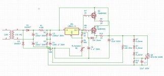
Well I have an update. Much LTspice simulating, head scratching, pacing back and forth and getting distracted by other projects has lead to the following schematic. I ditched the LR8 since I want more than 450V and it offers more of a learning experience. Simulations look good. Adjustable current limiting will be done through a 5 ohm rheostat, and will be about that accurate. All I use adjustable current limiting for is to minimize the damage if a DUT shorts. Three pass elements in parallel should keep them well within their DC SOA, especially with the current limiter.
Transformer tap switching will be implemented using a voltage doubler which conveniently has a point at 50% voltage. I know this does not have the best regulation. To compensate, I will likely use a very beefy transformer and some rather oversize caps.
Also to minimize the chances of nuking the FETs, I'm going to add a 1A fuse and a current limiting resistor after the last filter capacitor bank.
No device is 100% safe or reliable (especially one that can source 500V), but I feel that this has fairly reasonable margins and an adequate number of safety mechanisms for something like this. But let's also remember that it's a 500V power supply. It is not to be operated by those who are unaware of its dangers, and the operator must always remember that if it can source 500V across the output, then it's probably best to assume that it always has 500V present on the output.
What isn't shown (because I haven't drawn it yet) is the control board which will monitor heatsink temperature (and adjust fan speed) as well as disconnect the output in a fault condition (crowbar triggers, over temperature, mouse nest, etc). It will also handle all of the "transformer tap" switching.
Edit: Sorry for the ugly schematic- it's still a work in progress.
Attachments
Perhaps IGBTs are the devices to choose for high voltage, not MOSFETs, as they are more robust. Standard ratings are 600V and 1200V. Not normally used linearly though, but ought to work as well as MOSFETsMuch digging through the Digikey catalog turned up this part as a reasonably priced option for the pass elements. I think that a pair of these FQA8N90C-F109 1000V MOSFETs would probably be sufficient.
I went down this road many years ago. I designed a supply and built a small test version, but never built the complete supply. The test board with one Fet could withstand a short at full output.
I was looking for around 600 volts at at least 1 amp. I now have two commercial supplies that I got cheap that do 650 volts at 1.7 amps, so this dropped off my project list.
Use these mosfets. They are good for 600 volts, 600 watts, and 43 amps! I had 4 of them wired in parallel on a reasonably large heat sink. A thermal cutout switch from an air conditioning compressor is mounted and wired to shut off AC power to the whole supply.
2Sk3681 at Allied Electronics & Automation, Inc
I believe that this is the correct LT spice file, but I have a whole directory full of various iterations.
There are two diff pairs that compare the current to a reference (left side with LTC6101 chip) and output voltage (right side). Either will pull current away from the pass device's gate. Everything from R8 on is not part of the supply, it is a transient load test.
Attachments
Lab supply, two channels 325V 200 mA and one 125V 100 mA.
Voltage and current adjustment.
Switch voltage transistors MOSFETs VT16,17,18, a step of about 120 volts.

The switch windings in the code 1-2-4 per relay, step 32 volts.

Форум РадиоКот • Просмотр темы - Схема шелестова
Voltage and current adjustment.
Switch voltage transistors MOSFETs VT16,17,18, a step of about 120 volts.
The switch windings in the code 1-2-4 per relay, step 32 volts.
Форум РадиоКот • Просмотр темы - Схема шелестова
Last edited:
Perhaps IGBTs are the devices to choose for high voltage, not MOSFETs, as they are more robust. Standard ratings are 600V and 1200V. Not normally used linearly though, but ought to work as well as MOSFETs
The SOA of IGBTs drops like a rock at high voltages- they're really designed for switching.
Tubelab,
That MOSFET you listed is interesting. There's no SOA in the datasheet though, and most 600V FETs that I looked at really can't take much current at 500V- are these better? They look like they might actually be old enough to take some decent current in their linear region.
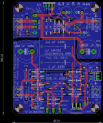
Some time ago I made power supply for my tube preamplifiers and amplifiers based on the Michael Maida high voltage regulator application note LB-47 from 1980 http://www.ti.com/lit/an/snoa648/snoa648.pdf , which of course since that date has been updated with a lot of new components with better specs which are available now, and Pete Millet designed an improved version with a MOSFET instead of a bipolar power transistor High Voltage Regulator and later Tom Christiansen made an other version with a better regulator 21st Century Maida Regulator, Rev. 2.0 ! My version is similar but since I am not familiar with SMD parts, I have designed a PCB for through hole parts, the result is very good
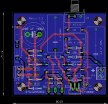
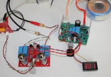
I made a version with a 6.3 V regulator for tube heater and a version with high voltage only for my lab power supply...
I strongly recommend this solution and for those that don't want to solder SMD like me, Tom even sell his version with these components already soldered
Marc
I made a version with a 6.3 V regulator for tube heater and a version with high voltage only for my lab power supply...
I strongly recommend this solution and for those that don't want to solder SMD like me, Tom even sell his version with these components already soldered
Marc
Attachments
600V FETs that I looked at really can't take much current at 500V- are these better?
I don't know, I haven't blown one up yet.
I have been using the 900 volt Fuji parts as output devices in a "darlington" configuration with a tube. The tube provides the characteristics while the mosfet does the heavy lifting. Haven't blown one of them up yet either.
These used to be stock items in the Allied Electronics catalog. They appeared in their "overstock clearance" pages maybe 10 years ago where they have been since. I bought a handful of these three parts back then and haven't blown one yet.
Note, that I haven't experimented with them since I got the HP6448B power supply. It's an old school 60 Hz "switcher" with a loop bandwidth of about 1Hz. It has 1000 uF of output capacitance which at 650 volts will blow stuff up real bad before the HP's current limiter even realizes that there is a problem.
Attachments
I just looked at the 900V rated Fuji parts... they're less than $2 each on Allied Electronics... those might be worth a shot. Same pinout as the other FETs I was looking at... intriguing.
I reconfigured the design a little bit so that RV1 varies the reference voltage. This seemed to linearize the output in relation to the position of the pot.
I "breadboarded" (more like heatsink and solder) a version of this using a single IRFP450 for the pass transistor. It does have a pretty serious overcompensation issue. When set to ~250V, with a .25A load (1000 ohm dummy load), the output voltage jumps to about 280 volts- not ideal.
I'm considering designing this power supply such that the pass transistors are on their own boar (4 per board) so that the design can be scaled up for other purposes
Attachments
Alright, this is long overdue for an update. To read the full story of how this design changed, you can read the EEVblog thread here
To make a long story short, the FETs could not handle this kind of load in a linear application. The FQA8N90C, which had a very promising DC SOA in the datasheet, was completely unable to handle more than 150mA with 500V across it. The 2SK3675 was even worse, but at least they didn't cost me much.
To make it work with a safety factor of 2, I was going to need at least at least seven or eight FETs. Current sharing was going to be a nightmare, and if even a single one shorted, the output would jump to the full 500V.
Also a big issue, with 10 devices in parallel (to get what I considered to be a reasonable safety factor), the gate capacitance would be on the order of 25nF, which would require a pretty low-impedance driver.
The solution was to use IRFP450s or IRFP460s in series. These ancient parts are robust and seem to handle linear operation better. In addition, with six FETs, no FET has to drop more than 100V across it (as we see later, it will never be more than half that). If a single part shorts, the others have to work harder to compensate, but the output doesn't immediately jump to 640V.
Transformer tap switching means that there should never be more than about 300V dropped across the series pass transistors. Because taps will be switched based on the actual output voltage, if the supply is set to output 500V, and it is shorted, the supply will current limit. This means, however, that the actual output will drop well below 300V, and the power supply will switch back down to the low range. This means, in theory, that the pass transistors will never have to drop more than about 60 volts across each device.
The best part? It uses relatively inexpensive transistors. The output is very quiet, even with a badly filtered DC bus (we're talking just a 25uF oil cap), the output noise is about 2mV, even under load when there's a good 10V of ripple on the DC bus. Once the external control circuitry (transformer tap switching, crowbar, heatsink temperature based fan control) is designed, this should be a solid bench supply that, if the builder is smart, doesn't have to cost much.
Attachments
Some remarks:
- The compensation looks very summary, and more problematically, it depends on the voltage setting: when the voltage is minimal, there is practically no compensation left, meaning the regulator is certainly not stable.
The wiper should be bypassed to the GND by a sufficiently large cap, and a resistor should be inserted in the - input of the opamp.
Even so, the stablity is probably not going to be very good, because of the large voltage gain of the VAS and the output pole.
- In case of an output short, C7 is sufficient to kill the opamp: protection diodes combined with a small series resistor should be added.
- The base of Q5 should be protected by a small series resistor (eg. 100 ohm)
- Status
- This old topic is closed. If you want to reopen this topic, contact a moderator using the "Report Post" button.
- Home
- Amplifiers
- Power Supplies
- HV bench power supply design