
Perhaps some confusion about what 'secondary' means. Your power transformer secondary winding should be connecting to the 'AC IN' vias on the pcb - marked as 'AC Input 2 pin' on the schematic.
Similarly, we would presume you would be probing the power supply output voltage at the "DC Out' J24 header for an actual ripple voltage measurement, although your soundcard plots and post text indicates you are probing at the output of some kind of 'audio processor' circuitry, which is perhaps on the same pcb.
If you have multiple external devices connected to your 'pcb', and more than one of those devices is connected to mains AC for powering, then you have to first ensure that you have no hum/noise loop induced signal polluting your soundcard measurement, otherwise you may be fooling yourself as to what you are seeing.
It seems your plug pack providing the raw AC to your pcb power supply is connected to the AC mains. To ensure there is no inadvertent hum/noise loop, you need to battery power everything else connected to that pcb (such as your probe and soundcard and PC) unless you have another form of isolating method that achieves the same thing.
It is also wise to do a calibration plot with the probe tip connected to its gnd terminal, and that node connected to your device under test, and confirm the True-RTA spectrum shows no hum or noise signals coming out of the noise floor.
As trobbins says, both wires from the secondary should be connected at the 'AC in' end of the board. This ensures that the charging pulse loop is reasonably small, and that you are not injecting ripple straight into your ground. If you connect one wire at the right end (to the rectifier diodes) and the other wire to the wrong end (PSU output ground) then significant ripple is what will happen. No amount of smoothing will get rid of this, yet simply moving the wire to the right place will solve it.
Increase C263 and C264.
Half wave rectification is essentially 50Hz so the caps discharge for twice as long as full wave rectification.
2200Uf would be better.
Don't snubber the didoes as that can add more noise into power supply.
If you get switching noise use Schottky's.
Half wave rectification is essentially 50Hz so the caps discharge for twice as long as full wave rectification.
2200Uf would be better.
Don't snubber the didoes as that can add more noise into power supply.
If you get switching noise use Schottky's.
In case anyone might be confused,
only applies to power transformers: ACmains input, DifferentVoltageDifferentCurrentAC output. (Higher voltage for valve gear, lower voltage for solid stage gear.) Switching power supplies don't contain a power transformer, which is a major reason why they're so small and so lightweight. But with no transformer these switching supplies need no transformer snubber. Whatever other circuits happen to be included inside a SMPS, you can be very sure that a transformer snubber is not among them.
Simple, no-math transformer snubber using Quasimodo test-jig
only applies to power transformers: ACmains input, DifferentVoltageDifferentCurrentAC output. (Higher voltage for valve gear, lower voltage for solid stage gear.) Switching power supplies don't contain a power transformer, which is a major reason why they're so small and so lightweight. But with no transformer these switching supplies need no transformer snubber. Whatever other circuits happen to be included inside a SMPS, you can be very sure that a transformer snubber is not among them.
Perhaps there is some misunderstanding creeping in for off-topic references to 'switching power supplies'.
This thread is about linear power supplies using a mains frequency power transformer.
Off-topic, but switchmode power supplies connected to the mains ac nearly always have a transformer, but that transformer operates at a high frequency. The parts around that transformer may or may not use a snubber to manage leakage inductance of transformer windings.
HI,
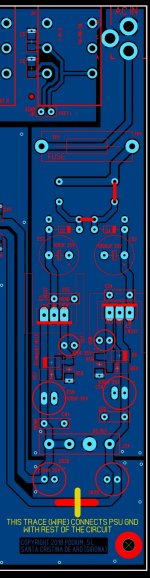
In my layout, the filter capacitor is connected to the same gnd plane as the rest of the psu. By layout, the filter capacitors are near the AC side, before regulators. Then come regulators and their associated feedback loop placed towards the DC output side, and the output caps.
Again, the yellow trace you can see in the picture, represents a thick copper wire that connects the PSU secondary ground to the ground plane of the rest of the circuit (not shown).
I recently measured ripple with a picoscope: and it seems normal, within the limits of what is possible with this kind of psu.
https://mikrosum.webnode.es/_files/200000020-6e38c6f325/VOLTAGE DOUBLER PSU RIPPLE IN MS.pdf
This is my first experience with this kind of psu. I always use to build typical center tapped dual supplies, very easy: I know where to connect ground wires to chassis, etc.
But with this psu... maybe it is not so clear. The audio jacks gnd in my layout are tied to chassis in the metal case. This way i have shielding protection. But the rest of the opamp circuit, only has the 0v reference back to the psu. So, ¿should i make a connection to chassis from the psu..? This device is powered by an AC-AC adapter 230ac in /18v ac out, with a barrel connector. Internal pin is AC power in, and external Barrel is tied to ground plane, (see picture).
I'm a bit confused. Thank you for your advise!
Jay x.
Attachments
Last edited:
Have you taken my advice, and correctly connected the secondary ground wire to the AC end of the PSU, and not to the DC end as you told me earlier? Connections of grounds to chassis are irrelevant at this point, as that is just for safety purposes.
If you don't understand what I am saying then please ask for clarification. Don't introduce other matters until you have this connection right.
If you don't understand what I am saying then please ask for clarification. Don't introduce other matters until you have this connection right.
Jay x you haven't provided clear information on the sound system and measurement system used for posts #14 and #9. You may have no hum or noise at all - it may just be the way you have made your measurements. Imho you need to provide details and a measurement system sketch/schematic and allow others to cross-check whether in fact you do have a problem or not.
HI DF96!
Maybe i don't understand you too well, sorry.
By secondary you refer to the transformer secondary ¿right? If you mean this, yes:
In the psu pcb there is an ac inlet for the barrel connector of the wall wart. One trace carries AC to the rectifier diodes, and the other two pins of the AC in connector are tied to the gnd plane.
As i maybe don't explain it too well, this is why i attached a picture, so you can see how i did the layout.
Jay x
Hi!
Finally i could solve the problems i had with the PSU. I made a proper connection to chassis, from the 0v DC output, and also rebuild the filter, with 2000uf/35v. Now the ripple is low, in the microvolt range. Besides, i revised many solderings.
Thank you for your advise!
Jay x.
Finally i could solve the problems i had with the PSU. I made a proper connection to chassis, from the 0v DC output, and also rebuild the filter, with 2000uf/35v. Now the ripple is low, in the microvolt range. Besides, i revised many solderings.
Thank you for your advise!
Jay x.
- Status
- This old topic is closed. If you want to reopen this topic, contact a moderator using the "Report Post" button.
- Home
- Amplifiers
- Power Supplies
- Half wave rectifier snubber