Hi Folks,
I‘m following this Thread for a while now and am overwhelmed by the Expertise and Mountains of Development efforts!
I hope my question is acceptable: For my application, an old LM317/LM337 based Phono-Preamp supply, which I want to keep, I‘d like to try one of the noise reducers developed here. But which one do I take?
Thanks for your advice!
Winfried
Depends. Is the power supply on a separate board? If you have the +/- rails on a separate pcb you can replace it with a dienoiser type pcb, there's two dual version here, smd and tht.
If not then you could add an add-on pcb for each rail, but I'd try to make the complete supply if possible.
If not then you could add an add-on pcb for each rail, but I'd try to make the complete supply if possible.
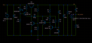
I tried to make a discrete regulator using the dienoiser for ac feedback. Seems to simulate ok. PSRR at around 93-95dB at 100Hz, output impedance at 1-2mOhm and .noise sim shows around 1nV/√Hz. I made two versions, a 1A one and 100mA one. I'm not sure if I made the temperature sim correctly but shows around 300mV between 25 and 75 degrees C. Vout delta between few mA and full load is around 200mV for the 1A version and around 40mV for the 100mA version. The min voltage across the pass transistor for full performance seems around 3.8-4V. I could tweak the difference in output voltage between light and full load but I think there's a balance with the PSRR.
I used MJE15032 for the 1A version and BCP56 for the 100mA version. For the reference I used a LM329. I tried to pulse the load and seems stable.
Seems like it should work, and performance seems interesting for a discrete regulator. Did I miss anything or is there anything simple that could improve the performance? Would it work in practice?
Attachments
Hello and thanks for the initial answer!Depends. Is the power supply on a separate board? If you have the +/- rails on a separate pcb you can replace it with a dienoiser type pcb, there's two dual version here, smd and tht.
If not then you could add an add-on pcb for each rail, but I'd try to make the complete supply if possible.
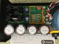
We are talking about retrofitting an existing, space limited, purchased power supply. Available space for an add-on is about 5x3x3cm. The 317/337 board (both on one PCB) shall remain, as it fits the case. I plan to piggy-back a known, well working noise reduction circuitry and do not plan to experiment or optimise beyond maybe tuning a potentiometer (as my expertise does not seem suffice beyond that...
 ).
).So I would be very thankful if I would be pointed to the posting(s) with the appropriate ciruitry, schematic or PCB, so I can take it on from there.
Thanks and Regards,
Winfried
Attachments
You could try the board in this post, I've tested it and it's working:
D-Noizator: a magic active noise canceller to retrofit & upgrade any 317-based V.Reg.
It's 43mm x 20mm. If you think you can solder the sot-23 parts there's a smd version as well.
D-Noizator: a magic active noise canceller to retrofit & upgrade any 317-based V.Reg.
It's 43mm x 20mm. If you think you can solder the sot-23 parts there's a smd version as well.
Thanks!
I'll have a look at the KiCAD project (got the S/W but only rudimentary experience with KiCAD...) and see what it tells me. Would boards be available for purchase at all? I'd just need two of the THT boards, as I have two of the power supplies.
Regards,
Winfried
I'll have a look at the KiCAD project (got the S/W but only rudimentary experience with KiCAD...) and see what it tells me. Would boards be available for purchase at all? I'd just need two of the THT boards, as I have two of the power supplies.
Regards,
Winfried
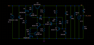
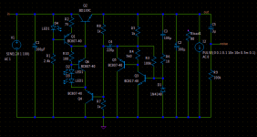
I have since improved it a bit. I used a cross between the nonoiser and dienoiser. I have also used some random led model I found, seems to perform worse than the ones in the library but seems to be having a closer Vdrop to the normal tht leds I have around.
Noise sim shows around 0.62nV/√Hz, PSRR around 120dB, and output impedance also dropped to around 0.5mOhm.
PSRR can be a bit higher with a LM329, or maybe a proper LED model. For the sim I used BD139 as pass transistor, I think it's a Bob Cordell model, around 100mA.
I tried to keep around 5mA going through the leds. To me the currents seem optimal, through the other components.
There's a delta of around 160mV between 25 and 75 degrees C for temperature sim.
Stepping the load between 10mA and 100mA there's a delta of around 120mV.
I guess figures could be improved a bit. I was in the middle of playing with the sim now. I pulsed the load and seems to recover nicely. I don't know if it needs compensation or ferrite bead like the NoNoiser.
I made a diy pcb of the previous version but I will do one for this version as well, seems like it should perform good. Considering the performance and price of components I think it's interesting.
Attachments
I think I can make the discrete regulator with even more accessible/cheaper parts.
Is there any more accessible part than LM317/LM337 on this planet? What is the real world benefit of this complexity comparing other concepts based on 3 pin regulators shared in this thread including yours? We have already discrete solutions like Salas and Jung Super Regs. Also, I think that the thread's most significant idea is making a simple alternative to the those complex discrete regulators.
When I think about that not a single 'complete' solution you were able to put on thread yet, now you are setting sails to the oceans of the discrete. I think that things are not going well on behalf of this thread.
I don't really see what you are mad about. This thread is mostly about the denoiser applied to LM317 and similar regulators. It's not about pcbs. I did them to help development mostly, and other users can benefit from them. But I have not insinuated my designs here, I also do not sell them. This is about the denoiser concept not about pcbs. I asked if I should make a separate thread for the pcbs but nobody said anything. So then you get what you get.
Also, most designs are complete and working. tht and smd add-on boards I've tested as working, I have tested the smd dual supply and since the single smd is included in the dual you can consider it also as tested. Today I made the V1.3 tht diy version that I'll test these days, it will most likely work like the others. For my designs I chose u.fl coax connectors if you want to remote sense for higher chances of success. I have not tested that yet, but that doesn't stop you from making any board and sensing on its output. What else do you want from my boards? Why don't you make any and tell us what the issues are since you consider them incomplete? I have invalidated previous designs, I only recommend the ones mentioned in the last posts.
Regarding the discrete regulator, I think it's very interesting. There's people that want discrete solutions. The Jung super-regs use an IC, this is pure transistor/diode based. Some might find it interesting.
The only pcbs of interest (three pin LM3x7/LT3082) I have not YET tested are in the mail, I'm waiting for them and I said I'll test them when I receive them. Do you wish for me to be silent in the meanwhile? I consider the cross between nonoiser and dienoiser with discrete regulator very interesting, I think it absolutely fits here.
edit: noise sim shows half the noise of a LM317+dienoiser. So theoretically it's better for a lower noisefloor, with similar PSRR.
2nd edit: Also the super-regs require a low-noise and usually expensive opamp. This doesn't need any IC.
Last edited:
I think it's best to consider my work as development, not finished products. This way I get faster results, I don't have time to "make them pretty" for beginners. I heavy-heartedly rounded the corners on the pcbs, but usually I make them for me. If you notice I try to make them DIY because it helps with making them faster. I do not do it to have boards to offer to people. I do them for research purposes. This way we found out faster what is needed to keep the LM337 dienoiser happy, the LT1085 dienoiser, LT3082 dienoiser, I tested the sot223 versions for LM3x7 and LT3082. And on the way some pcbs have been made public out of which some I tested. Some users might enjoy them. But I can't offer more time for beginner-friendly solutions. I barely have time to do all that I post here.
Again, my intention is not to make boards and offer them. I think you are mixing up my intentions with the ones of people that sell them or concentrate on a single design. I let others to make them more beginner friendly/pretty/audiophile friendly, tho I think they're pretty simple and functional.
If you want more end-user friendly solutions you should look at the VRDN board made by user Mark Johnson. It only has the denoiser option atm, and I think plain sense wires, but it looks nicer. I'm not sure if there's other designs, the VRDN is the only one I know.
I'll post the discrete version findings and also for the three legged pcbs when I receive them but I won't post designs anymore.
I will test it at first and see if it's worth making a new thread about it. If the performance is what the sim predicts and more people are interested maybe.
Also if others have questions about the designs here for LM3x7/LT3082 pcbs ask, I'll do my best to help. As far as I know the designs are complete. I'm not sure what terranigma meant with them being incomplete. At least the ones I recommended are complete, and they should cover most needs.
Also if others have questions about the designs here for LM3x7/LT3082 pcbs ask, I'll do my best to help. As far as I know the designs are complete. I'm not sure what terranigma meant with them being incomplete. At least the ones I recommended are complete, and they should cover most needs.
@Trileru, look at the first post of the thread. Elvee is an engineer (I don't know if he has done any academic stuff) and he is doing just what an engineer should do.
1. He comes up with an idea on his mind
2. Simulates it
3. Makes a prototype
4. Measures it
5. Proves it
6. Then shares it
If you had followed similar routine, no one would dare to criticize your efforts. Instead of that, you are flooding the thread with highly experimental stuff.
1. He comes up with an idea on his mind
2. Simulates it
3. Makes a prototype
4. Measures it
5. Proves it
6. Then shares it
If you had followed similar routine, no one would dare to criticize your efforts. Instead of that, you are flooding the thread with highly experimental stuff.
Last edited:
I think I proved the performance of the dienoiser with LM3x7, LT3082 and LT1085. What else do you want me to prove? Also there's some of the designs I've yet not tested. Your comments are in bad faith. These boards are not for you it seems, just don't make them. And don't know, maybe skip my comments? Wait for someone else to find out the same things I did, or wait for other boards? I don't really know what to tell you.
As I see it I rushed to find out information that will help others make boards for you. Sorry I didn't do it in a way that is comfortable for you. I really don't know what to tell you. Wait for someone else to make boards that are "complete". Mine are clearly not for you and I'm sorry about the bad experience.
I asked mods to delete some posts but they said they won't do it as they may be useful for others or the history of the project so I'm really at a loss.
If all you feel is frustration and you feel the need to vent because maybe the stuff here is too complicated then ok. I for one achieved the goals I set so I'm content.
Good luck with any board you decide to make/buy!
I think I proved the performance of the dienoiser with LM3x7, LT3082 and LT1085. What else do you want me to prove?
If you really think so, I won't ask anything further.
I certainly did, you can check the measurements in the previous posts. I made them for tht LM3x7, LT1085, smd LM3x7 and LT3082 the sot223 versions.
If anyone thinks I didn't I would like to know how/why they think that.
The sot223 devices were tested on the dual smd board and the tht devices were tested on the first tht board I made, I referenced it a few posts back. On the smd dual board I discovered the need for extra inductance for the LM337/LT3082/LT1085 dienoisers so they are stable with certain capacitors (ceramic and some electrolytics). You are free to test it yourself. As I said, if anyone thinks it doesn't work I'm curious of their test setup and willing to help them sort it out so it works for them as well.
- Home
- Amplifiers
- Power Supplies
- D-Noizator: a magic active noise canceller to retrofit & upgrade any 317-based V.Reg.