In fact, the add-on denoiser does not have force terminals: all the power is handled by the 317/337 and the GND coming from the supply, they provide the "force".My mistake, i followed the LV No-Noise schematic for the Kelvin connections...please correct me if this one is not suitable
Thus, you only have sense terminals to deal with, and to mimic a Kelvin-like connection, you just have to connect them as close as possible to the point of load.
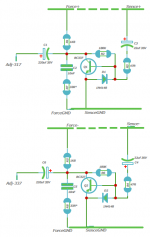
This is the corrected version: on the GND side, a direct, local connection between the compensation network and the emitter of the transistor is compulsory for stability.
On the "hot" side, the so-called "force" and "sense" (none is force in reality) terminals could be separated: it does cause problems, and having the 1K8 resistor connected to the regulator could give a microscopic advantage in terms of VLF impedance, but it is so tiny that I don't think it is worth adding a connection: just 3 connections will give an excellent performance and reduce the risk of confusion.
Attachments
I had forgotten that "magic" 33R resistor. I imagine it was abandoned because it didn't really improve things much.
I just simmed it, and the only thing it seems to affect a little is the impedance curve, but for the worst.
Is there something else it's supposed to do?
Another thing that using the Denoisator external board could bring an improvement, according to TNT audio excellent series on power supplies, is separating the parts connected to the 317/337 adjustment pin, that can now go to a ground point separate from the input ground, a principle that was also used on the Jung regulator.
Simple Voltage Regulators Part 2: Output Impedance
Attachments
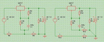
I was just noticing that to fulfill the separate grounds principle mentioned above, the adj pin to ground resistor would have to be connected to the Denoisator ground too.
A simple thing to do, and a good way to further improve most 3x7 regulators you will find, where that resistor is usually connected to the "common" and only ground, sometimes even a ground plane.
Am I exaggerating?
A simple thing to do, and a good way to further improve most 3x7 regulators you will find, where that resistor is usually connected to the "common" and only ground, sometimes even a ground plane.
Am I exaggerating?
How much less noise would be expected by using this replacement?I added the trace for 2SD2704 at the Bottom in case someone would like to test the board to replace the BC337
Yes and no: in AC, the correct connection of the denoiser (as downstream as possible) will swamp any effect of the resistor connection.I was just noticing that to fulfill the separate grounds principle mentioned above, the adj pin to ground resistor would have to be connected to the Denoisator ground too.
A simple thing to do, and a good way to further improve most 3x7 regulators you will find, where that resistor is usually connected to the "common" and only ground, sometimes even a ground plane.
Am I exaggerating?
If DC is also important (generally not in audio), moving the resistor downstream too will improve matters, but on the "hot" side, there is nothing you can do: moving R10 downstream will degrade things, not improve them meaning you are stuck with a 50% DC improvement.
Your guess is as good as mine: we cannot tell until it has been physically tested, because matters are generally more complicated than just a spice model.How much less noise would be expected by using this replacement?
The spice model looks promising, but it needs a real world confirmation.
If you use the denoiser, you are probably not going to see much difference anyway, because the noise floor is essentially dictated by the 317's noise performance (which is not included in the models I have seen).
With the Dienoiser/nonoiser, you should see a difference if it delivers on its promises
Ok, i forget the Kelvin Connection version and stay with the first version.just 3 connections will give an excellent performance and reduce the risk of confusion.
Thanks for your help..
THANK YOU for your efforts!! Just my 2¢ worth-----it's too big! Fitting a 60x35mm piece onto an existing board is tough, even splitting it in two. Could you make it smaller? (We probably could do without the 33Ω, for one). Just a thought....Thank Elvee..
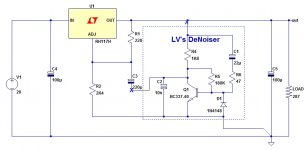
I added the 33R Optional D-Noizator: a magic active noise canceller to retrofit & upgrade any 317-based V.Reg.
PLEASE NOTE THIS PCB HAVE NOT BEEN TESTED YET...
I added the trace for 2SD2704 at the Bottom in case someone would like to test the board to replace the BC337
These are the smallest & best components I could find; some definitely smaller than what you show; P/Ns will work @ Mouser. Only ~80¢ per polarity!!
47 Ω resistor Metal Film Resistor - Through Hole 47ohms 1% 1/4 watt Xicon 271-47-RC 10@2.1¢ ea. 2.5 x 6.8 mm Axial
1.8K Ω resistor Metal Film Resistor - Through Hole 1.8Kohms 1% 1/4 watt Xicon 271-1.8K-RC 10@2.1¢ ea. 2.5 x 6.8 mm Axial
180K Ω resistor Metal Film Resistor - Through Hole 180Kohms 1% 1/4 watt Xicon 271-180K-RC 10@2.1¢ ea. 2.5 x 6.8 mm Axial
10nF capacitor MLCC Capacitors 0.01uF 50volts 10% X7R 2.5mm LS Vishay / BC Components K103K15X7RF53L2 14¢ ea. 2.5 x 4 mm Radial 2.5mm LS
22 µF capacitor Aluminum Electrolytic Capacitors - Radial Leaded 25volts 22uF 5x11 20% 2LS Nichicon UVR1E220MDD 10@11.6¢ ea. 5 x 11 mm Radial 2 mm LS
220 µF capacitor Aluminum Electrolytic Capacitors - Radial Leaded 220uF 25V 105c Nichicon UVY1E221MED1TD 10@21.1¢ ea. 6.3 x 11 mm Radial 2.5 mm LS
1N4148 diode Diodes - General Purpose, Power, Switching 100V Io/200mA ON Semiconductor / Fairchild 1N4148 10@6¢ ea. 2 x 4.5 mm Axial
BC-337-40 transistor Bipolar Transistors - BJT NPN 45V 800mA HFE/630 ON Semiconductor / Fairchild BC33740TA 10@20.5¢ ea. TO-92
OR BC-327-40 transistor Bipolar Transistors - BJT PNP 45V 850mA HFE/400 ON Semiconductor / Fairchild BC33740BU 10@19.4¢ ea. TO-92
Last edited:
Yes and no: in AC, the correct connection of the denoiser (as downstream as possible) will swamp any effect of the resistor connection.
If DC is also important (generally not in audio), moving the resistor downstream too will improve matters, but on the "hot" side, there is nothing you can do: moving R10 downstream will degrade things, not improve them meaning you are stuck with a 50% DC improvement.
Sorry, but what R10 are you talking about?
The resistor I suggested to connect to the Denoiser board was R2, and the arrangement to ground is the one I'm enclosing.
Attachments
I use the MFR series from Yageo..These are the smallest & best components I could find; some definitely smaller than what you show; P/Ns will work @ Mouser. Only ~80¢ per polarity!!
47 Ω resistor Metal Film Resistor - Through Hole 47ohms 1% 1/4 watt Xicon 271-47-RC 10@2.1¢ ea. 2.5 x 6.8 mm Axial
1.8K Ω resistor Metal Film Resistor - Through Hole 1.8Kohms 1% 1/4 watt Xicon 271-1.8K-RC 10@2.1¢ ea. 2.5 x 6.8 mm Axial
180K Ω resistor Metal Film Resistor - Through Hole 180Kohms 1% 1/4 watt Xicon 271-180K-RC 10@2.1¢ ea. 2.5 x 6.8 mm Axial
10nF capacitor MLCC Capacitors 0.01uF 50volts 10% X7R 2.5mm LS Vishay / BC Components K103K15X7RF53L2 14¢ ea. 2.5 x 4 mm Radial 2.5mm LS
22 µF capacitor Aluminum Electrolytic Capacitors - Radial Leaded 25volts 22uF 5x11 20% 2LS Nichicon UVR1E220MDD 10@11.6¢ ea. 5 x 11 mm Radial 2 mm LS
220 µF capacitor Aluminum Electrolytic Capacitors - Radial Leaded 220uF 25V 105c Nichicon UVY1E221MED1TD 10@21.1¢ ea. 6.3 x 11 mm Radial 2.5 mm LS
1N4148 diode Diodes - General Purpose, Power, Switching 100V Io/200mA ON Semiconductor / Fairchild 1N4148 10@6¢ ea. 2 x 4.5 mm Axial
BC-337-40 transistor Bipolar Transistors - BJT NPN 45V 800mA HFE/630 ON Semiconductor / Fairchild BC33740TA 10@20.5¢ ea. TO-92
OR BC-327-40 transistor Bipolar Transistors - BJT PNP 45V 850mA HFE/400 ON Semiconductor / Fairchild BC33740BU 10@19.4¢ ea. TO-92
https://www.mouser.fr/datasheet/2/447/Yageo LR_MFR_2013-467719.pdf
That is smaller that your recommendation.
I would definitely not using 25V capacitor, this is to low for 24V and up...(have to be universal use by the most of people as possible)
I am actually desinging a SMD/SMT board, that will may be answer to your need..
Elvee what do you thing BC807 in place of BC 327 and what SMD capacitor would you recommand?
Yes, you have a point. I was thinking along the lines of an 18-volt supply, since that is the most common maximum for opamps. But, I suppose there are other applications that would require 24 volts.I would definitely not using 25V capacitor, this is to low for 24V and up...(have to be universal use by the most of people as possible)
G'day guys,
From the feedback it seems as though Hicoco's board meets all of the necessary criteria so I won't attempt to duplicate the work. A very nice and tidy layout too. I doubt I could do better.
I will be very interested to see what feedback comes from the those who ordered boards off my gerbers.

I've had this guy making sweet noises for a month or so now with no issues. I however, lack any test equipment other than my 30 year old Fluke 25 and my ears.
If somebody has more appropriate gear like a good scope to poke around and check for instability I would be quite appreciative. Real world noise measurements would be fascinating.
From the feedback it seems as though Hicoco's board meets all of the necessary criteria so I won't attempt to duplicate the work. A very nice and tidy layout too. I doubt I could do better.
I will be very interested to see what feedback comes from the those who ordered boards off my gerbers.
I've had this guy making sweet noises for a month or so now with no issues. I however, lack any test equipment other than my 30 year old Fluke 25 and my ears.
If somebody has more appropriate gear like a good scope to poke around and check for instability I would be quite appreciative. Real world noise measurements would be fascinating.
Sadface,
Can you describe what is the regulator is powering on your photo?
A line preamp? Can you provide more info?
Sadface,
Can you describe what is the regulator is powering on your photo?
A line preamp? Can you provide more info?
Hi Carlmart,
Bang on. Its a line preamp. I wanted a simple solid state backup preamp that I can throw into my system while my tube preamp is on my bench for modification.
I wanted a nice small footprint as this old chassis is not large so I designed a single channel preamp board to stack on top of one another.
Nothing too fancy. A single LME49720 using both halves of the opamp.
Gain for both stages is set to 1.733x for a total gain of 3x minus the loss in the volume pot nested in between the 2 stages.


I originally designed the board to use an NE5532. However due to the use of the LME49720 I was able to omit the coupling caps.
I also found it necessary add a low pass filter on the input by soldering an extra 330pF ceramic cap on the underside of the board.
Eventually I will redesign the board to properly accommodate the input low pass filter. It has also been suggested that I add some E-562 constant current diodes across the supply rail and output pins to force the outputs into class A.
Perhaps you should try the original Elvee's advice on eliminating ceramic or film output
bypasses when using the Denoiser, and remove the 100n caps.
Using ICs that do not need coupling caps seems to be good move.
Could listen to any improvements after using the Denoiser?
Hi Carlmart,
These mono preamp boards have never been used with a psu other than the denoiser. Thus I could only compare the sound to earlier versions that also used a different signal stage.
Regarding the small bypassing ceramic caps. I have rather stuck with convention here as I still have far too much to learn. Every PSU implementation I looked at used small bypass ceramic or film caps across the larger electros. This could well be a case of the ignorant following the stupid, however I have discovered in my lifetime that I am both ignorant and stupid so I am not afraid to be wrong here.
Perhaps somebody with a scope could take some measurements of my denoiser board with and without the ceramic bypass caps just before the regs for comparison.
On my mono preamp board I ran with a datasheet implementation and TI recommends both the 10uF electro and the 100nF ceramic for best performance so that is what I did.
Where I did notice a huge gain in sound quality was the removal of the coupling caps and the addition of the RF filter. However I wasn't smart and did both of those changes at the same time so I cannot say which had the larger influence. A more scientific approach would have been to implement the changes separately but I am impatient.
Hi Carlmart,
I couldn't find the upload you mention in this thread. However I read through the article series but I am not certain which part in the series you refer to.
I think I might have misunderstood you previously. Are you referring to the 100nF ceramic caps before the regs or the 100nf bypass caps on the preamp board?
If we are talking about the bypass caps on the preamp board. I would have thought that the on board 10uF resovior cap and its ceramic bypass would ultimately increase the value of output bypass cap since they are ultimately in parallel?
Last edited:
D-Noizator: a magic active noise canceller to retrofit & upgrade any 317-based V.Reg.
I am talking about ceramic or film bypasses after the regulator.
I am talking about ceramic or film bypasses after the regulator.
- Home
- Amplifiers
- Power Supplies
- D-Noizator: a magic active noise canceller to retrofit & upgrade any 317-based V.Reg.